EasyManua.ls Logo

Sony SLV-LF1 User Manual

Sony SLV-LF1
77 pages
To Next Page IconTo Next Page
Page #1 background imageLoading...
Page #1 background image
Australian Model
SLV-LF1AS
Hong Kong Model
SLV-LF1MI
VIDEO CASSETTE RECORDER
RMT-V313/V313A
SLV-LF1
S MECHANISM
SLV-LF1
SERVICE MANUAL
123
456
789
0
VIDEO
Refer to the SERVICE MANUAL of VHS MECHANICAL
ADJUSTMENTS VI for MECHANICAL ADJUSTMENTS.
(9-921-647-11)
System
Color system
LF1MI:
PAL, MESECAM, NTSC 3.58,
NTSC 4.43
LF1AS:
PAL, NTSC 3.58, NTSC 4.43
TV system
LF1MI:
B/G, D/K, I, M
LF1AS:
B/G
Channel coverage
LF1MI:
B/G: VHF E2 to E12/UHF E21 to E69/
CATV S01 to S05, S1 to S41
D/K: VHF R1 to R12/UHF R21 to R69
I: VHF SA4 to SA13/UHF B21 to B69/
CATV S01 to S05, S1 to S41
M: VHF A2 to A13/UHF A14 to A69/
CATV A-8 to A-1, A to W, W+1 to W+84
LF1AS:
VHF AS0 to AS12, AS5A, AS9A
UHF AS28 to AS69
CATV S01 to S05, S1 to S41
RF output signal
LF1MI:
UHF channels 21 to 69
LF1AS:
UHF channels 28 to 69
Aerial out
75-ohm asymmetrical aerial socket
Inputs and Outputs
LINE-1 IN
VIDEO IN, phono jack (1)
Input signal: 1 Vp-p, 75 ohms, unbalanced,
sync negative
AUDIO IN, phono jack (2)
Input level: 327 mVrms
Input impedance: more than 47 kilohms
LINE OUT
VIDEO OUT, phono jack (1)
Output signal: 1 Vp-p, 75 ohms,
unbalanced, sync negative
AUDIO OUT, phono jack (2)
Standard output: 327 mVrms
Load impedance: 47 kilohms
Output impedance: less than 10 kilohms
General
Power requirements
110 - 240 V AC, 50/60 Hz (LF1MI)
220 - 240 V AC, 50 Hz (LF1AS)
Power consumption
16 W
Operating temperature
5°C to 40°C
Storage temperature
–20°C to 60°C
SPECIFICATIONS
Dimensions
Approx. 430 x 97 x 292 mm (w/h/d)
including projecting parts and controls
Mass
Approx. 4.6 kg
Supplied accessories
Remote commander (1)
R6 (size AA) batteries (2)
Aerial cable (1)
Plug adaptor (1) (LF1MI)
Design and specifications are subject to
change without notice.

Table of Contents

Question and Answer IconNeed help?

Do you have a question about the Sony SLV-LF1 and is the answer not in the manual?

Sony SLV-LF1 Specifications

General IconGeneral
BrandSony
ModelSLV-LF1
CategoryVCR
LanguageEnglish

Summary

SPECIFICATIONS

System and Signal Compatibility

Supported color systems, TV systems, and channel coverage.

Dimensions, Mass, and Accessories

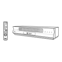
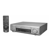
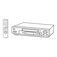
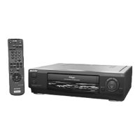
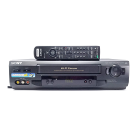
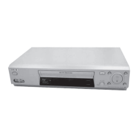
Physical size, weight, and included items of the VCR.

SAFETY CHECK-OUT

Pre-Release Safety Inspections

Checks to ensure VCR safety before customer return.

Component Safety Warnings

Caution regarding critical safety components.

GENERAL INFORMATION

Getting Started and Basic Operations

Initial setup and fundamental VCR functions.

DISASSEMBLY AND DIAGRAMS

Disassembly Procedures Overview

Steps for taking the VCR apart.

Block Diagrams and Schematics

Functional diagrams of VCR systems and circuits.

DISASSEMBLY DETAILS

Case, Panel, and Mechanism Removal

Procedures for disassembling the VCR's outer casing, front panel, and tape mechanism.

REMOTE COMMANDER SETUP

Battery Installation and Basic Use

How to set up and operate the remote for VCR and TV.

Controlling Other TVs

Programming the remote for compatibility with other TV brands.

TV AND VCR CONNECTION AND TUNING

Tuning Your TV to the VCR Signal

Connecting the aerial and tuning the TV to the VCR's output.

Presetting VCR Channels

Using automatic or manual tuning for VCR channels.

CHANNEL PRESETTING PROCEDURES

Automatic and Manual Channel Presetting

Detailed steps for setting up TV channels.

CHANNEL MANAGEMENT AND TROUBLESHOOTING

Disabling Unwanted Channels and Improving Picture

Skipping unused channels and fixing unclear pictures.

G-CODE SYSTEM SETUP

Setting Guide Channels for G-CODE

Matching VCR channels to G-CODE broadcast numbers for programming.

PROGRAMME POSITION MANAGEMENT

Changing and Disabling Programme Positions

Rearranging channel assignments and skipping unused ones.

SETTING THE CLOCK AND BASIC PLAYBACK

VCR Clock and Date Setup

Ensuring accurate time for timer recording functions.

Tape Insertion and Playback

Instructions for playing VHS tapes.

RECORDING TV PROGRAMMES

Basic Recording Procedures

Steps for starting, stopping, and managing recordings, including tape speed selection.

Recording While Watching Another Program

Procedure for recording one program while viewing another.

EASY TIMER RECORDING

Setting the Easy Timer and Clock

Programming single timer recordings and adjusting the VCR clock.

G-CODE SYSTEM RECORDING

Using G-CODE Numbers for Recording

Setting up recordings using broadcast guide numbers and frequency.

MANUAL TIMER SETTINGS AND PLAYBACK SEARCH

Manual Timer Setup and Options

Step-by-step guide for programming timer recordings and daily/weekly options.

Various Speed Playback and Search

Using different playback speeds and the index search function.

RECORDING DURATION AND TIMER MANAGEMENT

Setting Recording Duration and Timer Settings

Configuring auto-stop and managing timer settings.

STEREO AND BILINGUAL PROGRAMME RECORDING

ZWEITON/NICAM Handling and Sound Selection

Recording stereo/bilingual broadcasts and selecting audio tracks.

PICTURE ADJUSTMENT

Tracking, R², and APC Picture Enhancements

Adjusting tracking and using picture enhancement functions.

MENU OPTIONS AND SYSTEM CONNECTIONS

Changing Menu Options

Navigating and modifying VCR setup menu settings.

Connecting to Other Equipment

Diagrams for connecting to another VCR or stereo system.

INDEX TO PARTS AND CONTROLS

Remote Commander and Display Indicators

Overview of remote buttons and display symbols.

Rear Panel Connections

Description of the VCR's rear panel ports.

DISASSEMBLY SECTION

Case, Front Panel, and Board Disassembly

Procedures for removing the front casing and specific boards.

BLOCK DIAGRAMS SECTION

Overall Block Diagram

High-level functional overview of the VCR system.

SCHEMATIC DIAGRAMS

Frame Schematic Diagram

Overall circuit layout and interconnections.

PRINTED WIRING BOARDS

MA-402 Board Component Layout

Component placement for the main control board.

IC PIN FUNCTION DESCRIPTIONS

Video and Servo IC Pin Functions

Pin details for IC101 in video and servo blocks.

Mechanism IC Pin Functions

Pin details for IC101 in the mechanism block.

Audio IC Pin Functions

Pin details for IC101 in the audio block.

ERROR CODES

Error and Mode Code Descriptions

Explanations of VCR error and mode codes.

ADJUSTMENTS - PREPARATION

Electrical Adjustment Preparations

Instruments, connections, and setup for electrical adjustments.

ADJUSTMENTS - SEQUENCING AND POWER

Power Supply Adjustment and RF Switching

Procedures for adjusting power supply voltages and RF switching.

AUDIO SYSTEM ADJUSTMENTS

Hi-Fi Audio Calibration

Procedures for AF switching and frequency response checks.

Level, Distortion, and S/N Checks

Verifying audio levels, distortion, and signal-to-noise ratio.

TUNER SYSTEM ADJUSTMENT

Separation Adjustment

Calibrating audio channel separation in the tuner.

REPAIR PARTS LIST - EXPLODED VIEWS

Front Panel and Upper Case Parts

Illustrated breakdown of the front and top sections with part numbers.

Chassis Section Parts

Illustrated breakdown of the VCR's chassis with part numbers.

Mechanism Deck Parts

Illustrated breakdown of the mechanism deck with part numbers.

ELECTRICAL PARTS LIST

DM-98, FJ-33, and GK-12 Board Components

Component list for specific circuit boards.

MA-402 Board Components

Component list for capacitors, resistors, and ICs on the MA-402 board.

Related product manuals