Do you have a question about the Sony SLV-L45AR and is the answer not in the manual?
Technical specifications related to the system format, channels, and antenna.
General technical specifications including power, dimensions, mass, and included accessories.
Critical components identified by mark A are vital for safe operation and require specific Sony parts for replacement.
Instructions for connecting the video recorder to various audio/video and antenna systems.
Detailed steps for removing the cabinet, mechanism unit, and main board from the device.
Diagram showing the location of the main circuit boards within the VCR unit.
Connection diagram for the MC-1 mechanism unit.
Connection diagram for the MH drum head motor.
Connection diagram for the MC capstan motor.
Connection diagram for the MC-5 ACE head.
Overall wiring diagram for the mechanism section of the SLV-L45AR model.
Overall wiring diagram for the MC-1 unit.
Overall wiring diagram for the MH unit.
Overall wiring diagram for the MC unit.
Overall wiring diagram for the VP-1 unit.
Overall wiring diagram for the CP-1 unit.
Overall wiring diagram for the TM-1 unit.
Overall wiring diagram for the TM-2 unit.
Overall wiring diagram for the mechanism section of the SLV-L65HFAR/L75HFAR model.
Overall wiring diagram for the FE HEAD.
Overall wiring diagram for the MC-5 unit.
Overall wiring diagram for the MC-1 unit.
Overall wiring diagram for the MH unit.
Overall wiring diagram for the MC unit.
Overall wiring diagram for the VP-1 unit.
Overall wiring diagram for the CP-1 unit.
Overall wiring diagram for the TM-1 unit.
Overall wiring diagram for the TM-2 unit.
Diagram of the MPU for system control, OSD, timer, and tuning control.
Diagram of the MPU for system control, OSD, timer, and tuning control.
Audio circuit diagram for IC181 LA70011L.
Video circuit diagram for IC101(1/2) LA71501DM.
Video circuit diagram for IC181 LA70011L.
Audio circuit diagram for IC101 (1/2) LA71501DH.
Schematic diagram of the power supply circuit for the CP-1 PW-A board.
Video and audio circuit diagram for IC101 LA71501DM on the VA-A board.
Video and audio circuit diagram for IC101 LA71501DM on the VA-A board.
Video waveform at IC101 PIN14 during REC mode.
Video waveform at IC101 PIN15 during PLAY mode.
Video waveform at IC101 PIN18 during REC mode.
Video waveform at IC101 PIN25, 26 during REC/PLAY mode.
Video waveform at IC101 PIN28 during REC mode.
Video pre-amp circuit diagram for IC181 LA70011L.
Video pre-amp circuit diagram for IC181 LA70011L.
Table showing grid and segment assignments for the A7101 display.
Circuit diagram for the TM-1 board, covering operation key, display, and timer functions.
Printed wiring board layout for the TM-1.
Circuit diagram for TM-1 and TM-2 boards, detailing operation, display, and timer functions.
Printed wiring board layout for the TM-2.
Servo circuit waveform at IC301 PIN 23.
Servo circuit waveform at IC301 PIN 65.
Servo circuit waveform at IC301 PIN 24.
Servo circuit waveform at IC301 PIN 33,34.
Diagram for system control, servo, timer, and control MPU IC301.
Diagram for system control, servo, timer, and control MPU IC301.
Procedures for maintaining and checking the VCR mechanism for optimal performance and longevity.
Recommended regular checks and maintenance procedures to ensure full function and maximum performance.
Table detailing checks and maintenance items based on hours of use for various parts.
Instructions for cleaning the video head and tape path surface of the cylinder using methyl alcohol.
Cleaning procedures for tape path system components like pinch roller and reel drive system parts.
List of tools and their part numbers required for alignment and repair procedures.
Identification of the main parts within the VCR mechanism assembly.
Detailed view and naming of parts within the cassette mechanism assembly.
Table detailing mechanism modes, HEX data, and principal mode-switching states.
Important points to consider during disassembly and assembly of mechanism parts.
Methods for operating the loading motor to check mechanism movements.
Procedure for operating the loading motor using a DC voltage supply.
Procedure for manually operating the loading motor.
Method to make the mechanism move manually without operating the loading motor.
Steps for assembling the cassette mechanism, including notes on alignment and torque.
Procedure for removing and assembling the cylinder motor, rotor, and stator.
Procedure for removing and assembling the cylinder assembly, rotor, and stator.
Steps for removing and assembling the audio R/P head assembly (ACE HEAD).
Steps for removing and cleaning the full erase head.
Procedure for removing and assembling the capstan motor.
Procedure for removing the capstan brake assembly.
Procedure for removing and assembling the pinch roller lever assembly.
Procedure for removing and assembling reel belt, pulleys, gears, and clutch levers.
Procedure for removing and assembling the clutch mounting assembly.
Procedure for removing and assembling soft levers, supply reels, and reel gears.
Steps for removing S brake, T brake assemblies, and T brake act slide.
Procedure for removing and assembling the guide roller assembly.
Procedure for removing and assembling S and T incline mounting assemblies.
Procedure for checking the torque of the reel table in REW, FF, and PLAY modes.
Procedure for adjusting BT lever assembly position and checking back tension torque.
Steps to adjust the BT lever assembly position for proper back tension.
Method to check the back tension torque in PLAY mode using a cassette torque meter.
General procedure for tape path adjustment using an oscilloscope and alignment tape.
Procedure for adjusting the height of the load lever assembly using a special tool.
Procedure for adjusting the azimuth of the audio R/P head.
Procedure for adjusting the horizontal position of the audio R/P head.
Diagram showing the location of the main circuit boards for electrical adjustments.
Explanation of self-diagnosis numbers, problem codes, and corresponding mechanism operations.
Steps for basic VCR presetting using on-screen menus for connection and country selection.
List of test equipment and standards required for servo circuit adjustment.
Diagram showing the location of adjustment points on the CP-1 PWB for servo circuit adjustment.
List of test equipment and standards required for video circuit relay jig procedures.
List of test equipment and standards required for MTS decoder circuit adjustment.
Diagram showing the location of adjustment points for the MTS decoder circuit on the CP-1 PWB.
Required test equipment and standards for IF circuit adjustment.
Diagram showing the location of the adjustment point for the IF circuit.
Exploded view and parts list for the cabinet and chassis components.
Electrical parts list for the CP-A board, including notes on standardization and semiconductors.
| Brand | Sony |
|---|---|
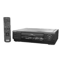
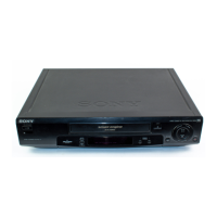
| Model | SLV-L45AR |
| Type | VCR |
| Video Format | VHS |
| Recording Speed | SP, LP, EP |
| Playback Speed | SP, LP, EP |
| Number of Heads | 4 |
| Remote Control | Yes |
| Connections | Composite Video |
| Inputs | Composite video, Audio |
| Outputs | Composite video, Audio |
| Dimensions | 360 x 96 x 228 mm |