Do you have a question about the Sony SLV-SX710 and is the answer not in the manual?
Summary of post-repair safety checks to perform before releasing the unit.
Critical warning regarding replacement of safety-critical components.
Initial setup procedures and user guidance for operating the VCR.
Procedure for removing the top cover of the VCR unit.
High-level block diagram illustrating the main functional sections.
Overall schematic diagram showing the basic circuit layout.
Details IC pin functions for the video block interface.
Explanation of error codes displayed on the unit.
Procedures for physical calibration of VCR mechanisms.
Procedures for electronic calibration of VCR circuits.
Visual diagram showing component locations for adjustments.
Visual representation of parts assemblies for identification.
Detailed list of electronic components with part numbers.
| Brand | Sony |
|---|---|
| Model | SLV-SX710 |
| Type | VCR |
| Video Format | VHS |
| Recording Speed | SP, LP, EP |
| Playback Speed | SP, LP, EP |
| Audio Output | Mono |
| Hi-Fi Stereo | Yes |
| Heads | 4 |
| Tuner | Yes |
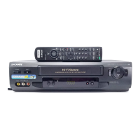
| Remote Control | Yes |
| Inputs | Composite video/audio, RF |