EasyManua.ls Logo

Sony SLV-SX25 User Manual

Sony SLV-SX25
75 pages
To Next Page IconTo Next Page
Page #1 background imageLoading...
Page #1 background image
AEP Model
SLV-SE10AE1/SE10AE2
UK Model
SLV-SE20UX/SE30UX/SE45UX
French Model
SLV-SE25B/SE40B
German Model
SLV-SE20VP1/SE20VP2/SE25VC
/SE30VC1/SE30VC2/SE40VC1
/SE40VC2/SE45VC/SX25VC
Spanish Model
SLV-SE25CP/SE30CP/SE40CP/SE45CP
East European Model
Greek Model
SLV-SE10EE/SE10EG/SE30EE/SE40EE/
SE40EG/SX10EG/SX40EG
Irish Model
SLV-SE20EX
SERVICE MANUAL
VIDEO CASSETTE RECORDER
MICROFILM
SLV-SE10/SE20/SE25/SE30/SE40/SE45/SX10/SX25/SX40
RMT-V256/V256A/V257/V257A/V257B/V257C/V259
j
Refer to the SERVICE MANUAL of VHS
MECHANICAL ADJUSTMENT
for
MECHANICAL ADJUSTMENTS. (9-921-647-11)
SPECIFICATIONS
Photo: SLV-SE45
RMT-V259
S MECHANISM
System
Channel coverage(10EE/EG/30EE/40EE/EG/
X10/X40 MODEL)
PAL(B/G,D/K):
VHF E2 to E12,R1 to R12
UHF E21 to E69,R21 to R69
CATV S1 to S41,S01 to S05
PAL(B/G):(10AE1/AE2/40B/25B/45CP/
30CP/VC1/VC2/20VP1/VP2/25CP/VC/40CP/
VC1/VC2/45VC/X25 MODEL)
VHF E2 to E12
VHF Italian channels A to H
UHF E21 to E69
CATV S01 to S05,S1 to S20
HYPER S21 to S41
SECAM(L):(SE25B/40B MODEL)
VHF F2 to F10
UHF F21 to F69
CATV B to Q
HYPER S21 to S41
PAL(B/G):
VHF E2 to E12
VHF Italian channels A to H
UHF E21 to E69
CATV S01 to S05,S1 to S20
HYPER S21 to S41
PAL (I)(20EX/UX MODEL)
VHFIA to IJ,SA10 to SA13(20EX only)
UHF B21 to B69
CATV S01 to S05,S1 to S20(20EX only)
HYPER S21 to S41
PAL (I)(SE30UX/45UX MODEL)
UHF B21 to B69
RF output signal
UHF channels 21 to 69
Aerial out
75-ohm asymmetrical aerial socket
Inputs and outputs
LINE-1
(TV)
21-pin
Video input: pin 20
Audio input: pins 2 and 6
Video output: pin 19
Audio output: pins 1 and 3
LINE-2 IN(10EE/30CP/VC1/VC2/EE/UX/
45CP/UX MODEL)
VIDEO IN, phono jack (1)
Input signal: 1 Vp-p,
75 ohms, unbalanced,sync negative
AUDIO IN,
phono jack (1)
Input level: 327 mVrms
Input impedance : more than 47 kilohms
LINE-2 IN(SE25VC/40VC1 MODEL)
21-pin
Video input: pin 20
Audio input: pins 2 and 6
LINE-2 IN
(25B/CP/VC/UX/40B/CP/VC1/VC2/45VC/
UX/X25 MODEL)
LINE-3 IN
(30CP/VC1/UX/VC2/45CP/UX)
21-pin
Video input: pin 20
Audio input: pins 2 and 6
LINE OUT(10EE/30EE/40EE)
AUDIO OUT,Phono jack(2)
Rated output level:327mVrms
Load impedance:47 kilohms
Output impedance:less than 10 kilohms
VIDEO OUT,Phono jack(1)
Rated output level:327mVrms
Load impedance:47 kilohms
Output impedance:less than 10 kilohms
General
Power requirements
220 - 240 V AC, 50 Hz
Power consumption
22 W
Operating temperature
5°C to 40°C
Storage temperatur
-20°C to 60°C
Dimensions
Approx. 355 x 96 x 285 mm(w/h/d)
including projecting parts and controls
Mass
Approx. 3.8 kg
(Approx. 10 lb 2 oz)
Supplied accessories
Remote commander (1)
R6 (size AA) batteries (2)
Aerial cable (1)
AC Plug adaptor(1)(20EX/UX)
Design and specifications are subject to change without
notice.
w
w
w
.
x
i
a
o
y
u
1
6
3
.
c
o
m
Q
Q
3
7
6
3
1
5
1
5
0
9
9
2
8
9
4
2
9
8
T
E
L
1
3
9
4
2
2
9
6
5
1
3
9
9
2
8
9
4
2
9
8
0
5
1
5
1
3
6
7
3
Q
Q
TEL 13942296513 QQ 376315150 892498299
http://www.xiaoyu163.com

Table of Contents

Question and Answer IconNeed help?

Do you have a question about the Sony SLV-SX25 and is the answer not in the manual?

Sony SLV-SX25 Specifications

General IconGeneral
BrandSony
ModelSLV-SX25
TypeVCR
Video FormatVHS
Recording SpeedSP, LP, EP
Playback SpeedSP, LP, EP
TunerYes
Number of heads4
Remote ControlYes
ConnectionsAV, RF
InputsComposite Video, Audio
OutputsComposite video/audio, RF

Summary

SPECIFICATIONS

General Specifications

Summary of key physical specifications, power requirements, and operating conditions.

Supplied Accessories

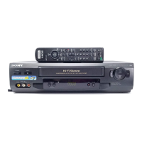
Lists all items provided with the VCR unit upon purchase.

SAFETY INFORMATION AND CHECKOUT

Safety-Related Component Warning

Highlights critical safety components for replacement.

Safety Check-Out Procedure

Essential verification steps to ensure unit safety before customer release.

GENERAL OPERATION AND SETUP

Unpacking and Initial Setup

Steps for unboxing the VCR and its accessories, and initial setup procedures.

Setting Up the Remote Commander

Guide to installing batteries and configuring the remote commander for VCR and TV operation.

Connecting the VCR to the TV

Instructions for connecting the VCR to a TV using various cable types for optimal signal.

Automatic VCR Setup Function

Procedure for automated channel tuning, setting configuration, and clock synchronization.

CHANNEL MANAGEMENT AND PROGRAMMING

Selecting On-Screen Language

Instructions for changing the VCR's on-screen display language from the available options.

Presetting and Disabling Channels

Guide to manually presetting channels and disabling unwanted ones to skip during tuning.

Timer Recording Setup

Setup for recording TV programs using timer functions, including Video Plus+ system.

BASIC AND ADVANCED OPERATIONS

Playing and Searching Tapes

Steps for playing tapes, searching content, and utilizing various playback speeds and functions.

Setting Personal Security Code

Procedure for setting a personal code for VCR identification and security purposes.

Smart Search and Index Search Functions

Utilizing Smart Search and Index functions to locate and playback recorded programs on tape.

PICTURE AND MENU ADJUSTMENTS

Picture Quality Adjustments

Guide to adjusting picture tracking and Optimum Picture Control (OPC) for optimal video output.

Changing VCR Menu Options

Instructions for modifying VCR settings through the menu system.

EDITING AND CONTROLS INDEX

Editing Tapes with Another VCR

Procedure for connecting two VCRs to record content from one to another.

Index to Parts and Controls

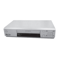
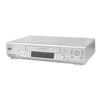
Locates and identifies all external controls and connection ports on the VCR.

SECTION 2 DISASSEMBLY PROCEDURES

External Component Removal

Step-by-step guide for removing the case, front panel, rear panel, and associated boards.

Internal Component Removal

Detailed steps for removing the mechanism deck and associated internal components.

Circuit Board Locations

Diagram showing the location of major circuit boards within the VCR unit.

SECTION 3 SYSTEM BLOCK DIAGRAMS

Overall System Block Diagram

High-level overview illustrating the interconnected functional blocks of the VCR system.

Video and Audio Signal Paths

Detailed block diagrams showing the signal paths for video and audio processing within the VCR.

Power Supply and Control System Diagrams

Block diagrams illustrating the power supply circuit and the servo/system control logic.

SECTION 4 SCHEMATIC AND WIRING DIAGRAMS

Frame Schematic Diagram

Schematic for the main unit frame.

MA-338 Board Schematics (1/9 to 9/9)

Detailed schematics for the main control board.

SECTION 5 IC PIN FUNCTION DESCRIPTIONS

IC Pin Functionality Overview

Comprehensive listing of IC pin functions, interfaces, and signal descriptions for VCR operation.

SECTION 6 ADJUSTMENTS AND CALIBRATION

Mechanical Adjustment Procedures

Procedures for performing mechanical adjustments, referring to specialized manuals.

Electrical Adjustment Procedures

Detailed steps for electrical adjustments, including power supply checks and system calibrations.

Power Supply Voltage Checks

Verifying crucial power supply voltages for proper VCR operation.

Servo System Adjustments

Calibrating the tape transport system for optimal performance.

Audio System Adjustments

Calibrating audio output levels and frequency response.

Adjusting Parts Location Diagram

Diagram to locate adjustment points on the circuit boards.

SECTION 7 REPAIR PARTS LIST

VCR Component Exploded Views

Illustrated exploded views to visually identify VCR components and their assembly.

Front Panel and Upper Case Parts

List of components for the VCR's front panel and upper case assembly.

Mechanism Deck Parts

Comprehensive list of parts for the VCR's tape mechanism assembly.

Electrical Parts List

Detailed listing of all electronic components, including part numbers and specifications.

Related product manuals