EasyManua.ls Logo

Sony SRP-V200 User Manual

Sony SRP-V200
26 pages
To Next Page IconTo Next Page
Page #1 background imageLoading...
Page #1 background image
1
Table of Contents
Warning
Notice for the Customers in the United Kingdom
IMPORTANT
The wires in this mains lead are coloured in accordance with the
following code:
Blue:Neutral
Brown:Live
As the colours of the wires in the mains lead of this apparatus may
not correspond with the coloured markings identifying the terminals
in your plug, proceed as follows:
The wire which is coloured blue must be connected to the terminal
which is marked with the letter N or coloured black. The wire which
is coloured brown must be connected to the terminal which is
marked with the letter L or coloured red. Do not connect either wire
to the earth terminal in the plug which is marked by the letter E or
by the safety earth symbol Y or coloured green or green-and-yellow.
AUDIO MIXER
SRP-V200
Operating instructions
Before operating the unit, please read this manual and the supplied “WARNING”
thoroughly and retain it for future reference.
Precautions
On safety (Refer to the supplied “WARNING”.)
Should any liquid or solid object fall into the cabinet, unplug the unit and
have it checked by qualified personnel before operating it any further.
• Unplug the unit from the wall outlet if it is not to be used for an extended
period of time. To disconnect the cord, pull it out by grasping the plug.
Never pull the cord itself.
On installation
• Do not install the unit in a location near heat sources such as radiators or
air ducts, or in a place subject to direct sunlight, excessive dust, mechanical
vibration or shock.
On operation
• Before making program source connections, be sure to turn the power
switch off and unplug the unit.
• When the unit is not used, turn the power off to conserve energy and to
extend the useful life of your unit.
On cleaning the cabinet
Clean the cabinet, panel and controls with a soft cloth lightly moistened with
mild detergent solution. Do not use any type of abrasive pad, scouring powder
or solvent such as alcohol or benzine.
On repacking
Do not throw away the carton and the packing material. It makes an ideal
container for transporting the unit.
When shipping the unit for repair work or to another location, repack it as it
was.
If you have any questions or problems concerning your unit, please contact
your nearest Sony dealer.
©1999 by Sony Sound Tec Corporation
2-346-938-11 (2)
Warning ............................................. 2
Main characteristics......................... 3
Dimensions ....................................... 3
System Configuration ...................... 14
Video Editor Connection ................. 18
Block diagram................................... 24
Main specifications .......................... 25
Name and function of each parts.... 4
MONO INPUT section......................... 4
STEREO INPUT section ..................... 6
MONITOR section............................... 8
MASTER section ................................ 10
INTERFACE section ........................... 11
BACK PANEL...................................... 12
Question and Answer IconNeed help?

Do you have a question about the Sony SRP-V200 and is the answer not in the manual?

Sony SRP-V200 Specifications

General IconGeneral
Frequency Response20Hz - 20kHz
Phantom Power+48V (switchable)
EQ3-band per channel
Power SupplyAC adapter
Inputs2 XLR/TRS combo, 2 RCA
Outputs1 XLR, 1 RCA, 1 headphones

Summary

Operating Instructions and Precautions

Precautions and Handling Guidelines

Covers safety, installation, operation, cleaning, and repacking guidelines.

Safety Warnings

General Electrical Safety

Essential safety warnings to prevent fire or electrical shock hazards.

Product Characteristics

Key Features and Inputs/Outputs

Details on the unit's input and output capabilities and signal types.

Microphone Powering

Information about the phantom power supply for condenser microphones.

Video Editor Integration

Explanation of remote control capabilities via a parallel interface.

Mounting Options

Information on rack mounting compatibility and an optional table kit.

Product Dimensions

Mono Input Section Details

Mono Input Controls and Functions

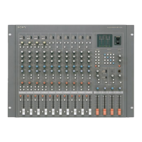
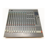
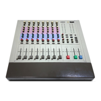
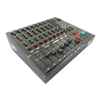
Detailed description of the mono input section controls and functions.

Stereo Input Section Details

Stereo Input Controls and Functions

Detailed description of the stereo input section controls and functions.

Monitor Section Details

Monitor Section Controls and Operation

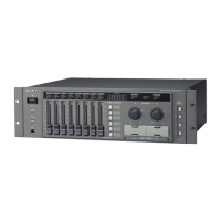
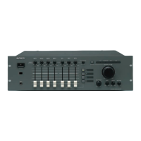
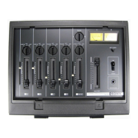
Overview of the monitor section controls and their functions.

Master and Monitor Section Details

Monitor Section Operations

Further details on monitor section controls like oscillator and mic.

Master Section Operations

Details of the master section controls, including AUX MASTER and MASTER Faders.

Interface Section Overview

Rear Panel Connector Guide

Back Panel Connector Explanations

Explanation of rear panel connectors including mono, stereo, monitor, and master outputs.

System Configuration: 2-Channel VTR Fixed

2-Channel VTR Fixed Recorder Assignment

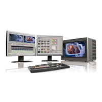
Configuration for editing systems using 2-channel VTRs with fixed recorder assignment.

System Configuration: 4-Channel VTR Fixed

4-Channel VTR Fixed Recorder Assignment

Configuration for editing systems using 4-channel VTRs with fixed recorder assignment.

System Configuration: 2-Channel VTR Free

2-Channel VTR Free Recorder Assignment

Configuration for editing systems with 2-channel VTRs and free recorder assignment.

System Configuration: 4-Channel VTR Free

4-Channel VTR Free Recorder Assignment

Configuration for editing systems with 4-channel VTRs and free recorder assignment.

Video Editor Integration Guide

Connecting to PVE-500 Editor

Details on connecting the SRP-V200 with the PVE-500 video editor.

Connecting to BVE-2000 Editor

Information on connecting the SRP-V200 with the BVE-2000 video editor.

Video Editor Integration Guide

Editor Connector Pin Assignments

Pin assignments and functions for editor connectors like VCA and monitor inputs.

Remote Connector Information

Remote Connector Pin Assignment

Pin assignment and function details for the remote connector.

System Block Diagram

Technical Specifications

Related product manuals