32
HT-RT3
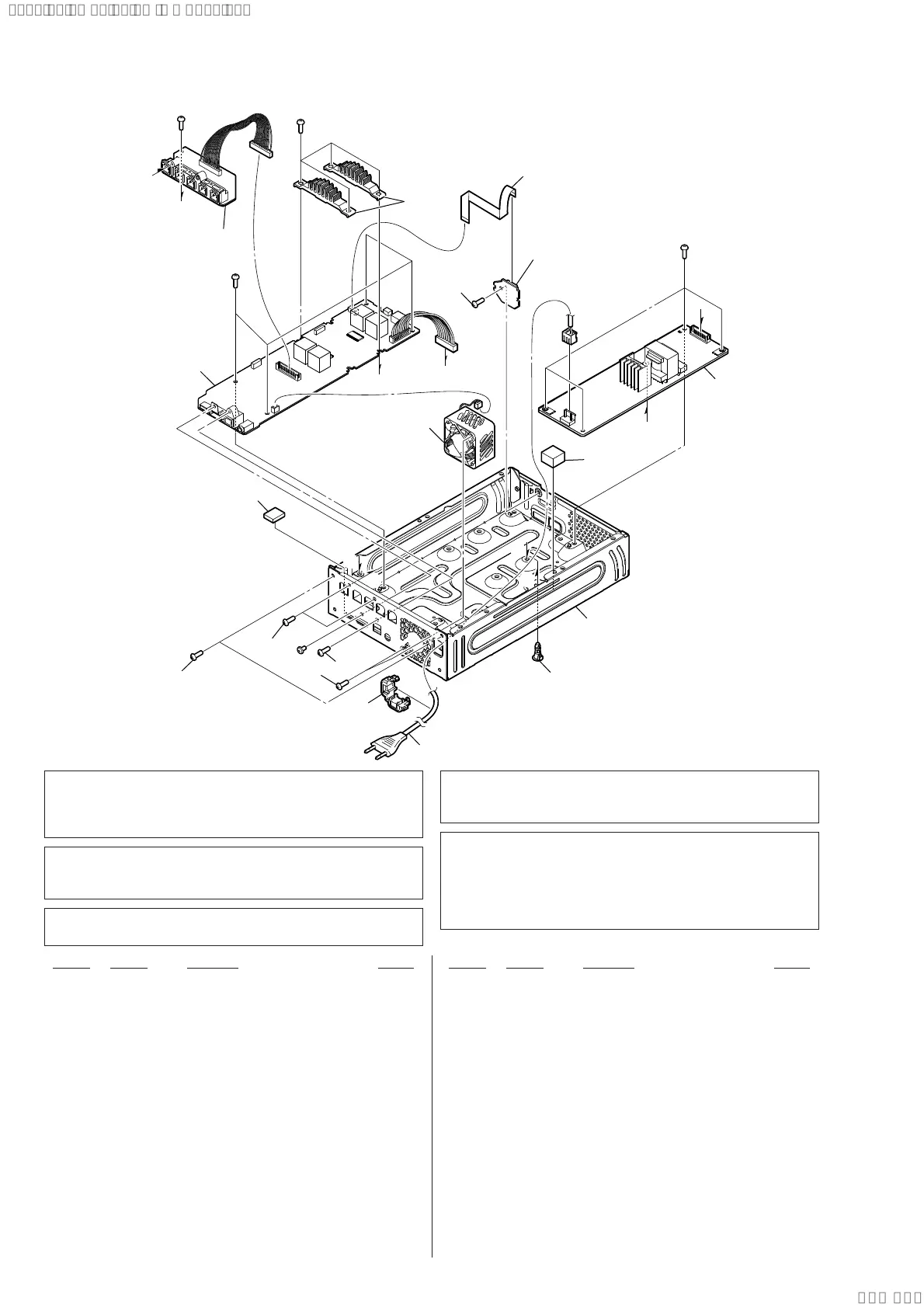
6-3. MAIN BOARD SECTION
Ref. No. Part No. Description Remark Ref. No. Part No. Description Remark
101 3-077-331-41 +BV3 (3-CR)
0 102 1-855-244-11 DC FAN
9 103 A-2107-088-A MAIN BOARD, COMPLETE (for SERVICE)
(US, CND)
9 103 A-2107-150-A MAIN BOARD, COMPLETE (for SERVICE)
(Former type: AEP) (See Note 5)
9 103 A-2107-150-B MAIN BOARD, COMPLETE (for SERVICE)
(New type: AEP) (See Note 5)
9 103 A-2107-159-A MAIN BOARD, COMPLETE (for SERVICE)
(Former type: UK) (See Note 5)
9 103 A-2107-159-B MAIN BOARD, COMPLETE (for SERVICE)
(New type: UK) (See Note 5)
9 103 A-2107-210-A MAIN BOARD, COMPLETE (for SERVICE) (E12)
9 103 A-2107-762-A MAIN BOARD, COMPLETE (for SERVICE) (AUS)
9 103 A-2107-776-A MAIN BOARD, COMPLETE (for SERVICE) (SP)
9 103 A-2107-842-A MAIN BOARD, COMPLETE (for SERVICE) (LA9)
9 103 A-2107-983-A MAIN BOARD, COMPLETE (for SERVICE) (AR)
9 103 A-2119-853-A MAIN BOARD, COMPLETE (for SERVICE) (EA)
104 1-828-228-51 WIRE (FLAT TYPE) (20 CORE)
0 105 4-966-267-12 BUSHING (FBS001), CORD
0 106 1-834-966-42 POWER-SUPPLY CORD (AEP, SP, LA9)
0 106 1-835-068-21 CORD, POWER (AUS)
0 106 1-837-308-12 CORD, POWER-SUPPLY (US, CND)
0 106 1-837-312-11 CORD, POWER-SUPPLY (AR)
0 106 1-839-999-22 POWER-SUPPLY CORD (UK, EA)
0 106 1-848-053-12 POWER-SUPPLY CORD (E12)
0 107 1-474-638-11 REGULATOR, SWITCHING 3L405W-2
(EXCEPT E12)
0 107 1-474-638-21 REGULATOR, SWITCHING 3L405W-3 (E12)
#1 7-685-646-71 SCREW +BVTP 3X8 TYPE2 IT-3
#3 7-682-546-09 SCREW +B 3X5
ns not supplied
Note 3: If wire (fl at type) is replaced, install it after bending it in
the same form as that before replacement.
Note 1: When the complete MAIN board is replaced, refer to
“NOTE OF REPLACING THE IC1000 AND IC1002
ON THE MAIN BOARD AND THE COMPLETE MAIN
BOARD” on page 5.
Note 2: When the REGULATOR, SWITCHING 3L405W board
is replaced, spread the bond referring to “BOND FIXA-
TION OF ELECTRIC PARTS” on page 6.
Note 4: When the complete MAIN board is replaced, spread
the bond referring to“BOND FIXATION OF ELECTRIC
PARTS” on page 6.
C
C
D
E
A
B
B
E
A
D
#1
#1
#1
#3
#1
ns
102
105
104
101
101
101
101
101
107
106
ns
SPEAKER CHUKEI PC
BOAR board (ns)
ns
ns
ns
CONNECTOR board (ns)
103
(See Note 5)
Ver. 1.6
(AEP, UK only)
Note 5: The complete MAIN board (Ref. No. 103) of AEP and
UK has been changed in the midway of production.
Refer to “CHANGE OF MAIN BOARD AND INSTRUC-
TION MANUAL” on page 5 for “Former type” and “New
type”.
SYSSET
2021/01/2802:06:46(GMT+09:00)