Do you have a question about the Sony SSC-DC132P and is the answer not in the manual?
Explains the manual's purpose and scope for color video cameras.
Lists additional manuals provided for the unit.
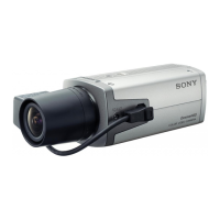
Provides essential instructions for operating the color video camera.
Details components and their functions on the front, side, and rear of the camera.
Guides for lens compatibility, fitting, and connection to the camera.
Steps for connecting power and video signals for different camera models.
Details the process for removing major parts like the front and filter blocks.
Guide for replacing the power cord on the SSC-DC138P model.
Explains the function and operation of key internal boards like BI-149, DCP-33, FC-85.
Describes the operation of power supply and control boards like AC-172, VCA-6, PS-601.
Lists required equipment, connections, and commander setup for adjustments.
Outlines general methods, initial data writing, VCO, and camera mode setup.
Covers VSUB, VPG, SYNC Level, Burst Level, SET UP, and 0 dB adjustments.
Details adjustments for AGC, White Balance, and Color Reproduction.
Steps to verify the results of performed adjustments like SYNC, Burst, SET UP, AGC, WB, Color.
Important notes and warnings regarding replacement parts for safe operation.
Visual representation of camera parts for identification and ordering.
Lists diodes and transistors with corresponding page or ID numbers for reference.
Visual representation of the camera's internal circuitry and board locations.
Detailed electrical schematics for the camera's main components.
Diagrams showing component placement on various circuit boards.
| Effective Pixels | 440, 000 pixels |
|---|---|
| Lens Mount | C mount |
| Minimum Illumination | 0.7 lx (F1.2, 50 IRE) |
| S/N Ratio | 50 dB |
| Video Output | Composite video output (BNC) |
| Power Supply | DC 12V |
| Image Sensor Type | CCD |
| Power Requirements | DC 12 V |
| Image Sensor | 1/3-type CCD |
| Electronic Shutter | 1/50 to 1/100, 000 sec |
| Operating Temperature | -10°C to +50°C (14°F to 122°F) |