Do you have a question about the Sony STR-AV370X and is the answer not in the manual?
Details power output and total harmonic distortion for amplifier section.
Covers amplifier section, harmonic distortion, frequency response, and inputs.
Details FM/AM tuner performance and audio output characteristics.
Explains methods to test AC leakage from exposed metal parts.
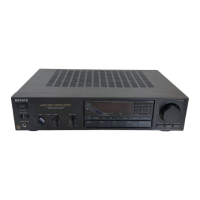
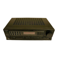
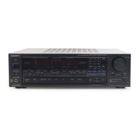
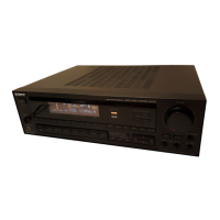
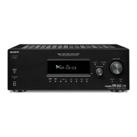
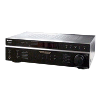
Identifies and describes the function of the unit's controls and remote commander.
Guides on how to tune FM/AM stations automatically or by direct frequency entry.
Explains manual AM tuning and how to memorize and recall preset stations.
Details procedures for FM discriminator, stereo level, and separation adjustments.
Provides guidance on replacing ceramic filters for FM IF offset adjustment.
High-level overview of the unit's functional blocks and signal flow.
Illustrates circuit board locations and semiconductor lead configurations.
Shows physical layout and electrical schematics for the main section.
Shows physical layout and electrical schematics for the tuner section.
Detailed explanation of the functions assigned to each pin of IC301.
Disassembled view of the front panel components with part numbers.
Disassembled view of the chassis components with part numbers.
Lists electrical components for the power, stand-by, and display sections.
Lists electrical components for volume, main, tone, speaker, muting, and HP sections.
Lists electrical components for main, tone, speaker, muting, HP, and tuner sections.
Lists electrical components for main, tone, speaker, muting, HP, and tuner sections.
Lists electrical components for main, tone, speaker, muting, and HP sections.
Lists electrical components for main, tone, speaker, muting, and HP sections.
Lists electrical components for main, tone, speaker, muting, HP, and tuner sections.
Lists electrical components specifically for the tuner section.
Lists miscellaneous wires, accessories, packing material, and hardware.
| Tuning range | FM: 87.5 - 108 MHz, AM: 530 - 1710 kHz |
|---|---|
| Power output | 60 watts per channel into 8Ω (stereo) |
| Frequency response | 10Hz to 50kHz |
| Total harmonic distortion | 0.08% |
| Dimensions | 430 x 135 x 310mm |
| Weight | 7.4kg |
| Input sensitivity | 150mV (line) |
| Speaker load impedance | 8 ohms |