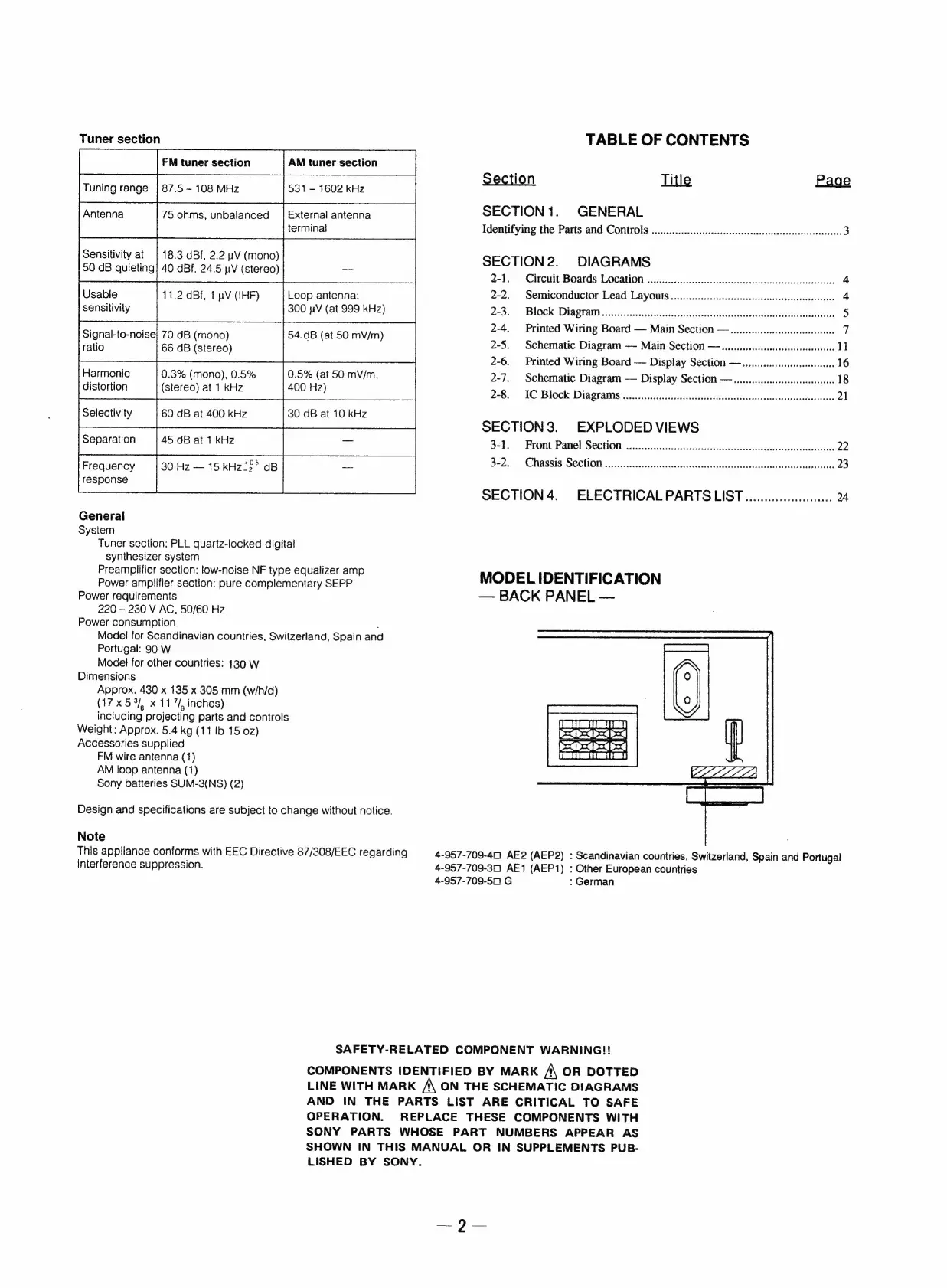
Tuner
section
Tuning
range
|
87.5
~
108
MHz
531
-
1602
kHz
Antenna
75
ohms,
unbalanced
|
External
antenna
terminal
Sensitivity
at
|
18.3
dBf,
2.2
uV
(mono)
50
dB
quieting!
40
dBf,
24.5
pV
(stereo)
Usable
11.2
dBi,
1
pV
(IHF)
Loop
antenna:
sensitivity
300
pV
(at
999
kHz)
Signal-to-noise|
70
dB
(mono)
54.dB
(at
50
mV/m)
ratio
66
dB
(stereo)
Harmonic
0.3%
(mono),
0.5% 0.5%
(at
50
mV/m,
distortion
(stereo)
at
1
kHz
400
Hz)
Selectivity
60
dB
at
400
kHz
30
dB
at
10
kHz
Separation
45
dB
at
1
kHz
Frequency
30
Hz
—
15
kHz
22°
dB
response
General
System
Tuner
section:
PLL
quartz-locked
digital
synthesizer
system
Preamplifier
section:
low-noise
NF
type
equalizer
amp
Power
amplifier
section:
pure
complementary
SEPP
Power
requirements
220
—
230
V
AC,
50/60
Hz
Power
consumption
.
Model
for
Scandinavian
countries,
Switzerland,
Spain
and
Portugal:
90
W
Model
for
other
countries:
130
W
Dimensions
Approx.
430
x
135
x
305
mm
(w/h/d)
(17x5%,
x
11
/,
inches)
including
projecting
parts
and
controls
Weight: Approx.
5.4
kg
(11
Ib
15
0z)
Accessories
supplied
FM
wire
antenna
(1)
AM
Ioop
antenna
(1)
Sony
batteries
SUM-3(NS)
(2)
Design
and
specifications
are
subject
to
change
without
notice.
Note
This
appliance
conforms
with
EEC
Directive
87/308/EEC
regarding
interference
suppression.
TABLE
OF
CONTENTS
Section
Title
Page
SECTION
1.
GENERAL
Identifying
the
Parts
and
Controls
......0...ccccccccsscscessscsecsessesssesecsceeescseseeseaes
3
SECTION
2.
DIAGRAMS
2-1.
Circuit
Boards
Location
0.0...
cccesscscesessscsssccsesvecsvecesseacscrsseneeeas
4
2-2.
Semiconductor
Lead
Layouts
.......ccccccccccssccscccssssessesceaceseceesseeeeces
4
22S,
*
BLOCK:
Dia
Sr
aM
asses)
chess
es
deacsieetiatis
head
eases
eased
eae
doeade
5
2-4.
Printed
Wiring
Board
—
Main
Section
—......ccce.cesscseseeseseesees
7
2-5.
Schematic
Diagram
—
Main
Section
—.......cccccsescssseeeeseserees
11
2-6.
Printed
Wiring
Board
—
Display
Section
—.....0...cccceeeeeees
16
2-7.
Schematic
Diagram
—
Display
Section
—
ou...
eceseeesseeeeee
18
2-8.
IC
Block
Diagrams
.........ccccccssssssssscssessssssssscescerceseenerseeeeens
nes
21
SECTION
3.
EXPLODED
VIEWS
3-1.
Front
Parel
Section
wiccccccccccescscesssesessccecssecessecscsesscesacsesescecerenes
22
3-2.
Chassis
Section
......c.ccccccssssssssscscscescssesssssscescccsacscsesccecsarseeseresees
23
SECTION
4.
ELECTRICALPARTS
LIST...................00.
24
MODEL
IDENTIFICATION
—
BACK
PANEL
—
4-957-709-40)
AE2
(AEP2)
:
Scandinavian
countries,
Switzerland,
Spain
and
Portugal
4-957-709-301
AE1
(AEP1)
:
Other
European
countries
4-957-709-5001
G
:
German
SAFETY-RELATED
COMPONENT
WARNING!!
COMPONENTS
IDENTIFIED
BY
MARK
A
OR
DOTTED
LINE
WITH
MARK
A
ON
THE
SCHEMATIC
DIAGRAMS
AND
IN
THE
PARTS
LIST
ARE
CRITICAL
TO
SAFE
OPERATION.
REPLACE
THESE
COMPONENTS
WITH
SONY
PARTS
WHOSE
PART
NUMBERS
APPEAR
AS
SHOWN
IN
THIS
MANUAL
OR
IN
SUPPLEMENTS
PUB-
LISHED
BY
SONY.