EasyManua.ls Logo

Sony STR-GX215 Service Manual

Sony STR-GX215
31 pages
To Next Page IconTo Next Page
Page #1 background imageLoading...
Page #1 background image
STR-GX210/GX810/GX415
SERVICE
MANUAL
AEP
Model
STR-GX215/GX3
15/GX415
East
European
Model
STR-GX215/GX315
UK
Model
STR-GX315
PHOTO:
STR-GX415
SPECIFICATIONS
Amplifier
section
AEP1,
German,
90W+90W
70W+70W
East
European,
(4ohms)
(4ohms)
UK
model
80W+80W
50W+50W
DIN,
IkHz
(80hms)
(80hms)
80W+80W
70W+70W
50W+50W
(80hms)
(80hms)
(80hms)
40Hz-20kHz
THD
0.3%
Harmonic
distortion
Less
than
0.8%
at
rated
output
Frequency
response
PHONO:
RIAA
equalization
curve
+0.5dB
CD
VIDEO
|
10Hz-50kHz
‘3
dB
TAPE
Input
Sensitivity
Impedance
S/N
(weighting
network,
input
level)
PHONO
2.5mV
50kilohms
75d
B(A
net)
75dB*(A
net,
5.0
mV)
CD,
VIDEO,
|
250mV
5O0kilohms
82dB
(A
net)
TAPE
1,2
82dB*(A
net
500mV)
*78
THF
Outputs
REC
OUT,
Voltage
250mV
VIDEO
(AUDIO)
OUT
Impedance
10kilohms
HEADPHONES
Accepts
low
and
high
impedance
head
phones
Tone
controls
BASS:
£10dB
at
100Hz
TREBLE:
+10dB
at
10kHz
Loudness
+6dB
(100Hz)
MICROFILM
Tuner
section
Tuning
range
87.5-108MHz
531-1602kHz
Antenna
75ohms,
unbalanced
Sensitivity
at
18.3dBf,
2.2nV
(mono)
41dB
quieting
40d
Bf,
24.5yV
(stereo)
Usable
sensitivity
11.2d
Bf,
1pV
(IHF)
Loop
antenna:
300pV
(at
999kHz)
Signal-to-noise
ratio
70dB
(mono)
/66dB
(stereo)
|
54dB
(at
50mV/m)
Harmonic
distortion
0.3%
(mono),
0.5%
0.5%
(at
50mV/m,
(stereo)
at
1kHz
400
Hz)
60dB
at
400kHz
30dB
at
10kHz
Frequency
response
30Hz—15kHz
“3°
dB
|
General
System
Tuner
section:
PLL
quartz-locked
digital
synthesizer
system
Preamplifier
section:
low-noise
NF
type
equalizer
amp
Power
amplifier
section:
pure
complementary
SEPP
Power
requirements
220-230V
AC,
50/60Hz
240V
AC,
50/60Hz
(U.K.
model)
Power
consumption
ara
STR-GX415
STR-GX315
STR-GX215
AEP1,
German
model
|
230W 200W
160W
AEP2,
East
European,
|
165W
130W
110W
UK
model
—Continued
on
next
page—
FM
Stepeo
FM-AM
Receiver
SONY.
FM
tuner
section
AM
tuner
section
£
8
Ei
=z
Question and Answer IconNeed help?

Do you have a question about the Sony STR-GX215 and is the answer not in the manual?

Sony STR-GX215 Specifications

General IconGeneral
Input Sensitivity150 mV (line)
Tuning rangeFM, MW
Speaker load impedance8 ohms
Speaker Impedance8 ohms
Total Harmonic Distortion0.08%
Dimensions430 x 130 x 300mm

Summary

Receiver Specifications Overview

Amplifier Section Performance

Details power output, distortion, frequency response of the amplifier.

Tuner Section Performance

Details sensitivity, selectivity, and signal-to-noise ratio of the tuner.

Input/Output and Tone Control Details

Specifies impedance, S/N, and tone control ranges for inputs and outputs.

Power Requirements and Consumption

Lists power supply needs and operational power draw of the receiver.

Receiver General Information and Front Panel Controls

Receiver Dimensions, Weight, and Accessories

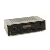
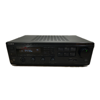
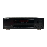
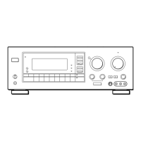
Details physical specifications and included items for the receiver.

Model Identification and Safety Warnings

Explains model variants and critical component safety warnings.

Front Panel Controls and Indicators

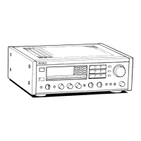
Identifies all buttons, lights, and displays on the front panel.

Receiver Electrical Adjustment Procedures

FM Signal Level Display Adjustment

Procedure for adjusting the FM signal level display.

IC Pin Functions and Block Diagrams

System Control IC Pinout

Lists pinout details for the main system control IC (UPD78043GF-SOX4072).

Receiver System Block Diagram

Illustrates signal flow and component relationships within the receiver.

Circuit Board and Semiconductor Layouts

Circuit Boards Location

Diagrams showing the physical placement of various circuit boards.

Semiconductor Lead Layouts

Visual representation of common semiconductor pinouts.

Main Board Schematic Diagrams

GX215 Main Board Schematic

Detailed circuit diagram for the GX215 main board.

GX315/GX415 Main Board Schematic

Circuit diagram for the GX315 and GX415 main boards.

Display Section Schematics and IC Details

Printed Wiring Boards - Display Section

PCB layout for display components.

IC Block Diagrams and Waveforms

Explains IC functions and signal behavior in the display system.

Printed Wiring Boards Layouts

Main Section Printed Wiring Boards

PCB layout for the main board.

Power, SW, Transformer, and HP Boards

PCB layouts for ancillary boards like Power, SW, Transformer, and HP.

Main Board Wiring and Semiconductor Locations

Main Section Printed Wiring Board

Detailed PCB layout for the main board.

Semiconductor Location Table

Cross-references semiconductor part numbers to board locations.

Other Board Layouts and IC Details

Display Section Printed Wiring Boards

PCB layout for the display section.

Vol, Tone, and Standby Boards

PCB layouts for the Vol, Tone, and Standby boards.

Exploded Views of Receiver Components

Cabinet Section Exploded View

Illustrates the assembly of the receiver's cabinet.

Chassis Section Exploded View

Shows the assembly of the internal chassis components.

Electrical Parts List: Components

Introduction, Notes, and Abbreviations

Explains list conventions and component types.

Capacitors, Connectors, Diodes, Switches, ICs, and Transistors

Lists core electronic components like capacitors, connectors, diodes, switches, ICs, and transistors.

Electrical Parts List: Resistors and Coils

Resistor Part Numbers and Specifications

Details various carbon and wirewound resistors.

Coil Part Numbers

Lists various coils used in the circuit.

Electrical Parts List: Semiconductors and Special Components

Transistor, Diode, and IC Part Numbers

Lists semiconductor components including transistors, diodes, and ICs.

Transformers, Fuses, Relays, Vibrators, and Encapsulated Components

Lists specialized components and power parts like transformers, fuses, relays, vibrators, and encapsulated units.

Related product manuals