EasyManua.ls Logo

Sony STR-GX390 Service Manual

Sony STR-GX390
28 pages
To Next Page IconTo Next Page
Page #1 background imageLoading...
Page #1 background image
STR-GX290/6X390
SERVICE
MANUAL
AEP
Model
Photo
:
STR-GX290
SPECIFICATIONS
Amplifier
section
Continuous
RMS
power
output
STR-GX390
:
50W
+50W(8
ohms:
AEP/4
ohms:
Germany,
at
40Hz—
20kHz
less
then
0.7%
total
harmonic
distortion)
STR-GX290
:
30W
+
30W(8
ohms:
AEP/4
ohms:
Germany,
at
40Hz—
20kHz
less
then
0.7%
total
hamonic
distortion)
Dynamic
power
(DIN)
.
STR-GX390
:
SOW
+50W
(8
ohms:
AEP/4
ohms:
Germany,
at
1KHz
0.7%)
STR-GX290
:
30W+30W(8
ohms:
AEP/4
ohms
:Germany,
at
1KHz
0.7%)
Dynamic
power
(IEC)
STR-GX390
:
50W
+50W(8
ohms:
AEP/4
ohms
:
Germany,
at
1KHz
0.7%)
STR-GX290
:
30W
+
30W(8
ohms:
AEP/4
ohms:
Germany,
at
1KHz
0.7%
)
Harmonic
distortion
less
then
0.7%
at
rated
output
Frequency
response
PHONO:
RIAA
equalization
curve
£0.5dB
CD
VIDEO
|
10Hz—S50kHz
*?
dB
TAPE
Inputs
ane
Sensitivity
Inpedance
S/N
(Weighting
network)
input
level)
|
74
dB
72
dB*
(A,
2.5
mV)
CD,
VIDEO
95
dB
TAPE
1,
2
eon
50
kohms
|
80
dB*
(A,
200
mv)
“78
IHF
Outputs
REC
OUT
Voltage
:200
mV
VIDEO
(AUDIO)
OUT
|
Impedance
10
kohms
SPEAKER
A,
B
Impedance
8
ohms
:
AEP/4
ohms
:
Germany—-16
ohms
HEADPHONES
Accepts
low
and
high
impedance
headphones
colts
Tone
controls
BASS:
£10dB
at
100Hz
TREBLE
:
£10dB
at
10kHz
Variable
loudness
contro!
+6dB
at
100Hz
(MAX)
FM
STEREO/FM-AM
RECEIVER
SONY.
Question and Answer IconNeed help?

Do you have a question about the Sony STR-GX390 and is the answer not in the manual?

Sony STR-GX390 Specifications

General IconGeneral
Power output55 watts per channel into 8Ω (stereo)
Frequency response10Hz to 50kHz
Total harmonic distortion0.08%
Input sensitivity2.5mV (MM), 150mV (line)
Signal-to-Noise Ratio76dB (MM), 100dB (line)
Dimensions430 x 135 x 310mm
Weight7.2kg
Speaker load impedance8 ohms

Summary

Specifications

IC Pin Functionality

IC Pin Functions

Lists pin numbers, signal names, functions, and I/O for the main IC.

Electrical Adjustments

FM Discriminator Adjustment Procedure

Procedure to adjust the FM discriminator for zero voltage output.

FM Stereo Operation Level Adjustment

Procedure to set the FM stereo operation level for optimal stereo reception.

FM Stereo Separation Adjustment

Procedure to adjust FM stereo separation for improved audio quality.

Diagrams and Layouts

Semiconductor Lead Diagrams

Provides pinout diagrams for various semiconductor components used in the device.

Electrical Parts List

Capacitor Parts List

Lists various capacitor types, part numbers, and specifications.
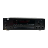
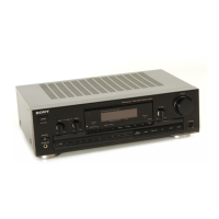
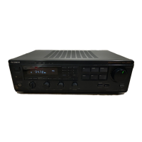
Related product manuals