Do you have a question about the Sony STR-GX211 and is the answer not in the manual?
Describes power output, distortion, and frequency response characteristics.
Covers tuning range, sensitivity, and signal-to-noise ratio for FM/AM reception.
Details impedance, sensitivity, voltage for inputs/outputs, and tone adjustment ranges.
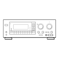
Describes front panel controls, buttons, indicators, and their functions.
Illustrates the physical placement of various circuit boards within the unit.
Shows pin configurations and orientations for semiconductor components.
Provides a high-level functional overview of the unit's signal flow.
Displays the layout and component placement on the main circuit board.
Shows the detailed electronic circuit schematic for the main section of the unit.
Displays the layout and component placement on the display circuit board.
Shows the detailed electronic circuit schematic for the display section of the unit.
Illustrates the internal logic and pin functions of integrated circuits.
Details the components and assembly of the front panel section.
Illustrates the assembly of internal chassis components and boards.
| Brand | Sony |
|---|---|
| Model | STR-GX211 |
| Category | Stereo Receiver |
| Language | English |