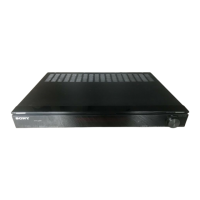
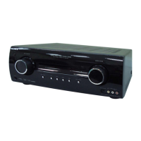
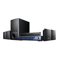
STR-KG800
2
1. SERVICING NOTES ............................................. 3
2. GENERAL .................................................................. 4
3. DISASSEMBLY
3-1. Disassembly Flow .......................................................... 9
3-2. Case ................................................................................. 9
3-3. Back Panel Block ............................................................ 10
3-4. Front Panel Block .......................................................... 10
3-5. Main Block ..................................................................... 11
3-6. MAIN Board ................................................................... 11
4. TEST MODE ............................................................ 12
5. ELECTRICAL CHECK ......................................... 14
6. DIAGRAMS
6-1. Block Diagram - MAIN Section - ................................... 15
6-2. Block Diagram - HDMI Section - ................................... 16
6-3. Block Diagram - DSP Section - ...................................... 17
6-4. Block Diagram - AUDIO Section - ................................. 18
6-5. Block Diagram - POWER SUPPLY Section - ................ 19
6-6. Printed Wiring Board - MAIN Board - ........................... 21
6-7. Schematic Diagram - MAIN Board (1/3) - ..................... 22
6-8. Schematic Diagram - MAIN Board (2/3) - ..................... 23
6-9. Schematic Diagram - MAIN Board (3/3) - ..................... 24
6-10. Schematic Diagram - DIGITAL AB Board (1/5) -.......... 25
6-11. Schematic Diagram - DIGITAL AB Board (2/5) -.......... 26
6-12. Schematic Diagram - DIGITAL AB Board (3/5) -.......... 27
6-13. Schematic Diagram - DIGITAL AB Board (4/5) -.......... 28
6-14. Schematic Diagram - DIGITAL AB Board (5/5) -.......... 29
6-15. Printed Wiring Board
- DIGITAL AB Board (Component Side) -..................... 30
6-16. Printed Wiring Board
- DIGITAL AB Board (Conductor Side) - ...................... 31
6-17. Printed Wiring Boards
- MIC/HEADPHONE Section - ...................................... 32
6-18. Schematic Diagram - MIC/HEADPHONE Section - ..... 33
6-19. Printed Wiring Board - HDMI Board (Side A) - ............ 34
6-20. Printed Wiring Board - HDMI Board (Side B) - ............ 35
6-21. Schematic Diagram - HDMI Board (1/2) - ..................... 36
6-22. Schematic Diagram - HDMI Board (2/2) - ..................... 37
6-23. Printed Wiring Boards - VIDEO Section - ..................... 38
6-24. Schematic Diagram - VIDEO Section - .......................... 39
6-25. Printed Wiring Boards - PANEL Section - ..................... 40
6-26. Schematic Diagram - PANEL Section - .......................... 41
6-27. Printed Wiring Board
- DCDC CONVERTER Board - ..................................... 42
6-28. Schematic Diagram
- DCDC CONVERTER Board - ..................................... 43
6-29. Printed Wiring Board - STANDBY Board - ................... 44
6-30. Schematic Diagram - STANDBY Board - ...................... 45
7. EXPLODED VIEWS
7-1. Front Panel Section ......................................................... 61
7-2. Back Panel Section ......................................................... 62
7-3. MAIN Section ................................................................. 63
8. ELECTRICAL PARTS LIST .............................. 64
TABLE OF CONTENTS
Notes on chip component replacement
• Never reuse a disconnected chip component.
• Notice that the minus side of a tantalum capacitor may be dam-
aged by heat.
SAFETY-RELATED COMPONET WARNING!
COMPONENTS IDENTIFIED BY MARK 0 OR DOTTED LINE
WITH MARK 0 ON THE SCHEMATIC DIAGRAMS AND IN
THE PARTS LIST ARE CRITICAL TO SAFE OPERATION.
REPLACE THESE COMPONENTS WITH SONY PARTS
WHOSE PART NUMBERS APPEAR AS SHOWN IN THIS
MANUAL OR IN SUPPLEMENTS PUBLISHED BY SONY.
General
Power requirements
Area code Power requirements
CEL, CEK 230 V AC, 50/60 Hz
Power output (DIGITAL MEDIA PORT)
DC OUT: 5 V, 0.7 A MAX
Power consumption
Area code Power consumption
CEL, CEK 200 W
Power consumption (during standby mode)
0.3 W (When “CONTROL
FOR HDMI” in VIDEO
menu is set to “CTRL
OFF”)
Dimensions (width/height/depth) (Approx.)
430 × 157.5 × 318 mm
including projecting parts
and controls
Mass (Approx.) 7.8 kg
Design and specifi cations are subject to change
without notice.