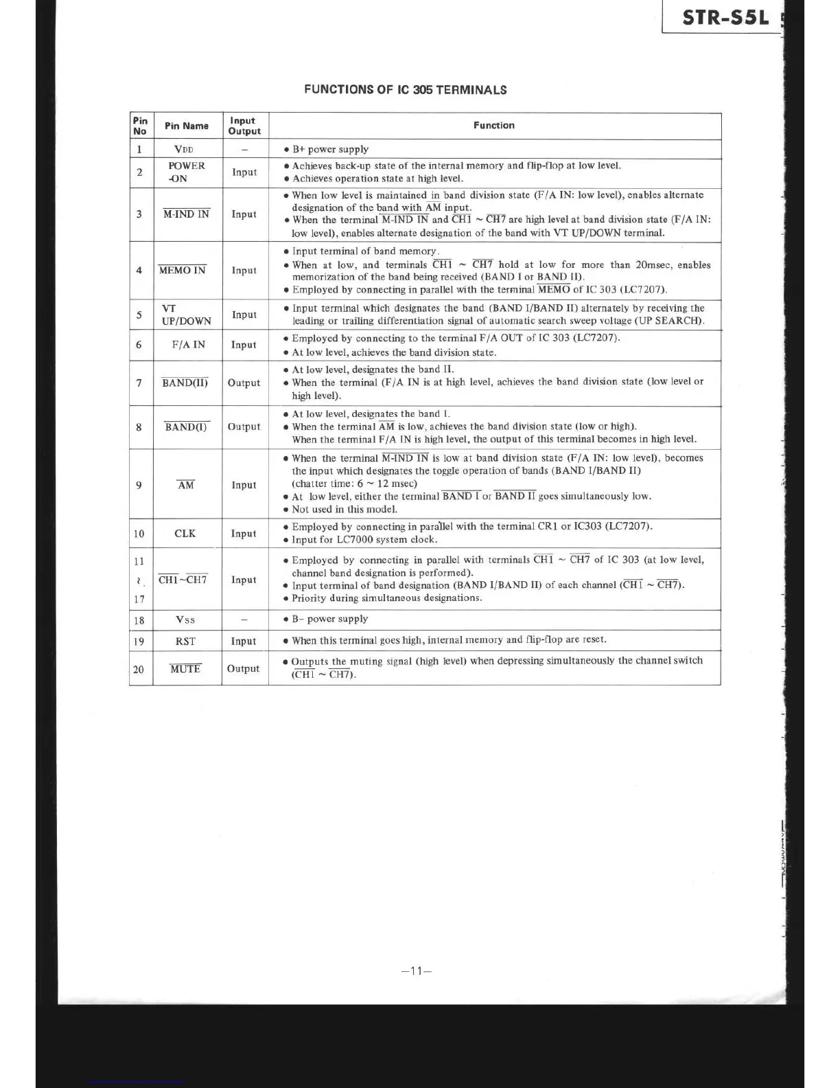
FUNCTIONS
OF IC
305 TERMINALS
Pin
No
Pin Name
Input
Outpul
Function
I Vno
.
B+
power
supply
2
PO\ryER
.oN
Input
o
Achieves back-up state of the internal
memory and flip-flop at low level.
o
Achieves operation
state at
high level.
3
I!-il.{D IN lnput
o
When low level is maintained
in band division state
(F/A
IN:
low level),
enables
alternate
designation of the band
with AM
input.
o
When the
terminal
M-IND IN
and
CHI
-
CH7 are high level at band division state
(F/A
IN:
low level),
enables
alternate designation
of
the band with VT
UPiDOWN
terminal.
4 MEMO IN
Input
.
Input terminal of band memory.
o
When at low,
and terminals eHl
-
CH7 trotd at low for more
than 2Omsec, enables
memorization of the band being received
(BAND
I or BAND II).
o
Employed by connecting in
parallel
with the terrninal
MEMO of IC
303
(LC'1207).
5
w
uP/DOWN
Input
.
Input terminal
which
designates the
band
(BAND
I/BAND II)
alternately by receiving
the
leading
or
trailing
differentiation signal of automatic search sweep
voltage
(UP
SEARCH).
6
F/A IN Input
r
Employed by connecting to the
terminal
F/A
OUT
of IC
303
(LC72O7).
.
At
low level, achieves
the band division state.
BAND-(ii)
Output
o
At low level,
designates
the band II.
r
When
the terminal
(F/A
IN
is at
high level, achieves
the band
division stâte
(low
level
or
high
level).
8
BAND(I)
Output
.
At low level, designates
the
band I-
.
When
the terminal
AM
is
low, achieves
the
band
division state
(low
or high).
When the terminal
F/A IN is high
level, the output of this terminal becomes in
high level.
9
AM
Input
r
When the terminal
Ni:IND-TN
is
low at band division state
(F/A
IN:
low level), becomes
the input
which
designates
the toggle operation
of
bands
(BAND
I/BAND II)
(chatter
time:
6
-
12
msec)
.
At
low level, either the terminalEÂNDI-orBA-ND-lf
goes
simultaneously low.
o
Not used in this model.
10
CLK
Input
o
Employed by connecting
in
paraÏel
with the
terminal CRI or IC303
(LC7207).
o
Input for LC7000 system clock.
11
l,
t'l
cHl-CH7
Input
o
Employed by connecting in
parallel
with terminals CHI
-
CH7
of IC
303
(at
low level,
channel band
designation is
performed)
.
Input terminal of
band designation
(BAND
I/BAND
II)
of each channel
(CH1
-
CH7).
o
Priority during simultaneous
designations.
18
Vss
o
B-
power
supply
t9
RST
Input
.
When
this terminal
goes
high, internal
memory and
flip-flop are
reset.
20
MUTE
Output
.
Outputs
the
muting signal
(high
level)
when depressing
simultaneously
the channel
switch
(cHl
-
cH7).
 Loading...