EasyManua.ls Logo

Sony TA-F590ES Service Manual

Sony TA-F590ES
32 pages
To Next Page IconTo Next Page
Page #1 background imageLoading...
Page #1 background image
_TA-FOSOES/F690ES
SERVICE
MANUAL
Amplifier
Section
Items
Photo
:
TA-F690ES
cc
SPECIFICATIONS
Conditions
Switzerland,
Spain
and
TA-F590ES
TA-F690ES
Continuous
RMS
power
output
(both
|
4
ohms,
Countries
other
than
|
110W+110W
125
W
+125
W
channels
driven
simultaneously)
20
Hz-—20kHz
Scandinavian
countries}.
(THD
0.01%)
(THD
0.01%)
(DIN:
130
W
+
130
W)
AEP
Model
UK
Model
Data
(DIN:
145
W
+
145
W)
Portugal
_|
6
ohms,
Scandinavian
countries)
90
W
+
90
W
100
W
+
100
W
20
Hz-20kHz
Switzerland,
Spain
and
(THD
0.006%)
(THD
0.006%)
;
Portugal
(DIN:
105
W
+
105
W)
(DIN:
110
W
+
110
W)
8
ohms,
Countries
other
than
85
W
+
85
W
95W
+95
W
20
Hz
—20
kHz
|
Scandinavian
countries}
(THD
0.004%)
(THD
0.004%)
Switzerland,
Spain
and}
(DIN:
95
W
+
95
W)
(DIN:
105
W
+
105
W)
Portugal
Scandinavian
countries}
80
W
+
80
W
85
W
+
85
W
Switzerland,
Spain
and
(THD
0.004%)
(THD
0.004%)
Portugal
(DIN:
90
W
+
90
W)
(DIN:
95
W
+
95
W)
Power
band
width
(IHF)
8
ohms,
THD
0.02%
10
Hz
100
kHz
at
45
W
10
Hz
100
kHz
at
45
W
|
Dynamic
headroom
(’78
IHF)
4
ohms
To
dB
2dB
8
ohms
1.2
dB
1.2
dB
6
=
4
Total
harmonic
distortion
8
ohms,
at
10
watt
output
0.005%
0.005%
Intermodulation
(IM)
distortion
4
ohms,
at
rated
output
0.008%
0.008%
|
6GOHz:7kHz=4:
1
r
6
ohms,
at
rated
output
0.006%
0.006%
8
ohms,
at
rated
output
0.004%
0.004%
[
Damping
factor
8
ohms,
at
1
kHz
>
|
100
100
MICROFILM
continued
on
next
page
INTEGRATED
STEREO
AMPLIFIER
SONY.
Question and Answer IconNeed help?

Do you have a question about the Sony TA-F590ES and is the answer not in the manual?

Sony TA-F590ES Specifications

General IconGeneral
TypeIntegrated amplifier
Total Harmonic Distortion (THD)0.008%
Damping factor100
Input Sensitivity150mV (line)
Weight12.3kg
Signal to noise ratio105dB (line)
Frequency Response2Hz to 100kHz
Output150mV (line)
Speaker load impedance4Ω - 16Ω
Dimensions430mm x 150mm x 400mm
Total Harmonic Distortion0.008% at 1kHz

Summary

SPECIFICATIONS

Amplifier Section Specifications

Technical performance details for the amplifier section.

GENERAL SYSTEM DETAILS

System Overview

Information on system weight, power requirements, dimensions, and notes.

SECTION 1. GENERAL

Function of Controls

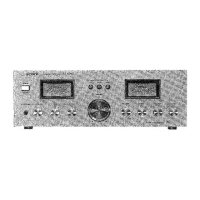
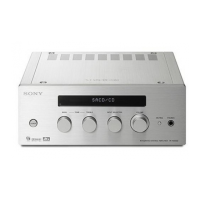
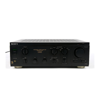
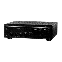
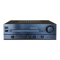
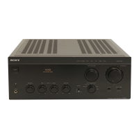
Detailed explanation of front and rear panel controls and their functions.

SECTION 2. ELECTRICAL ADJUSTMENTS

Bias Adjustment Procedure

Steps for adjusting amplifier bias settings for optimal performance.

SECTION 3. DIAGRAMS

IC803 System Controller Diagram

Pinout and description for the system controller IC.

Semiconductor Lead Layouts

Visual guides for common semiconductor component pin configurations.

Circuit Boards Location

Diagram showing the physical placement of various circuit boards within the unit.

IC Block Diagrams

Block diagrams illustrating the internal functions of key integrated circuits.

Block Diagram

High-level overview of the amplifier's signal path and component interconnections.

Printed Wiring Boards

Layout diagrams for specific sections of the amplifier's circuit boards.

Schematic Diagram (Control, Input, Selector, Vol Section)

Detailed circuit schematic for control, input, and volume sections.

Schematic Diagram (EQ, Main, SP Section)

Detailed circuit schematic for EQ, main, and speaker sections.

SECTION 4. EXPLODED VIEWS

Front Panel Section Exploded View

Exploded view of the front panel assembly, showing part numbers.

Sub Chassis Exploded View

Exploded view of the internal sub chassis assembly and its components.

Main Chassis Exploded View

Exploded view of the main chassis assembly, including major internal parts.

SECTION 5. ELECTRICAL PARTS LIST

Accessories & Packing Materials List

List of included accessories, packing materials, and manuals.

Hardware List

List of screws, nuts, and other hardware used in the unit's assembly.

Related product manuals