EasyManua.ls Logo

Sony TA-FB740R Service Manual

Sony TA-FB740R
26 pages
To Next Page IconTo Next Page
Page #1 background imageLoading...
Page #1 background image
1
AEP Model
UK Model
E Model
Australian Model
SPECIFICATIONS
SERVICE MANUAL
INTEGRATED STEREO AMPLIFIER
TA-FB740R
Amplifier section
DIN power output
100 W + 100 W (4 at 1 kHz)
60 W + 60 W (8 at 1 kHz)
Total harmonic distortion
Less than 0.008% (at 10 W output 1 kHz)
Frequency response
PHONO (20 Hz - 20 kHz): RIAA equalization curve
±0.5 dB
TUNER, SACD/CD, AUX, TAPE1/DAT, TAPE2/MD:
7 Hz - 300 kHz
+0
–3
dB
S/N (network A)
PHONO
TUNER, SACD/CD, AUX, TAPE1/DAT, TAPE2/MD:
105 dB
90 dB
Output voltage/impedance
REC OUT 1, 2: 150 mV, 1 k
PHONES: 10 mW (at 8 )
Speakers impedance
4 - 16 , 8 - 16 (SPEAKERS A+B)
Damping factor
500 (8 , 1 kHz)
General
System
Power amplifier: Pure-complementary SEPP OCL
power amplifier with all stages directly coupled
Preamplifier: Low-noise, equalizer amplifier
Power requirements
230 V AC, 50/60 Hz
Power consumption
180 W
Dimensions (approx.) (w/h/d)
430 × 150 × 420 mm
incl. projecting parts and controls
Mass (approx.)
8.6 kg
Supplied accessories
Remote commander (remote) (1) RM-S336
Sony batteries R6 (size-AA) (2)
Design and specifications are subject to change without
notice.

Other manuals for Sony TA-FB740R

Question and Answer IconNeed help?

Do you have a question about the Sony TA-FB740R and is the answer not in the manual?

Sony TA-FB740R Specifications

General IconGeneral
Input Sensitivity150 mV (line)
Signal-to-Noise Ratio86dB (MM)
Dimensions430 x 150 x 410mm
Speaker load impedance4 - 16 ohms
TypeStereo amplifier
Frequency Response10Hz - 100kHz (+0/-3dB)
Total Harmonic Distortion (THD)0.03%
Weight14.5 kg
OutputSpeaker A/B, Pre Out
Damping factor100 (8 ohms, 1kHz)

Summary

General Information and Panel Layouts

Front Panel Controls and Indicators

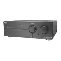
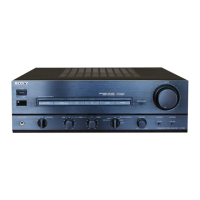
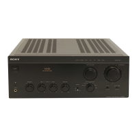
Detailed layout and function of front panel controls and indicators.

Rear Panel Connections and Ports

Detailed layout and function of rear panel connectors and controls.

Electrical Adjustment Procedures

Bias Adjustment Procedure

Step-by-step guide to adjusting bias for optimal performance.

Circuit Diagrams and Board Layouts

Circuit Boards Location Diagram

Diagram showing the physical placement of all internal circuit boards.

Input Section Schematic Diagram

Detailed circuit schematic for the input stage.

Input Section Printed Wiring Board

Layout of components and traces for the input board.

Electrical Parts List and Component Identification

Related product manuals