EasyManua.ls Logo

Sony TA-FB940R Service Manual

Sony TA-FB940R
26 pages
To Next Page IconTo Next Page
Page #1 background imageLoading...
Page #1 background image
1
AEP Model
UK Model
E Model
Australian Model
SPECIFICATIONS
SERVICE MANUAL
INTEGRATED STEREO AMPLIFIER
TA-FB940R
Photo: BLACK model
Amplifier section
DIN power output
120 W + 120 W (4 at 1 kHz)
Except UK, Singapore, Malaysia:
80 W + 80 W (8 at 1 kHz)
95 W + 95 W (4 at 1 kHz)
UK, Singapore, Malaysia model:
60 W + 60 W (8 at 1 kHz)
Total harmonic distortion
Less than 0.008% (at 10 W output 1 kHz)
Frequency response
PHONO (20 Hz - 20 kHz): RIAA equalization curve
±0.5 dB
TUNER, SACD/CD, AUX, TAPE1/DAT, TAPE2/MD:
7 Hz - 300 kHz
+0
–3
dB
S/N (network A)
PHONO
94 dB
TUNER, SACD/CD, AUX, TAPE1/DAT, TAPE2/MD:
105 dB
Output voltage/impedance
REC OUT 1, 2: 150 mV, 1 k
PHONES: 10 mW (at 8 )
Speakers impedance
4 - 16 , 8 - 16 (SPEAKERS A+B)
Damping factor
500 (8 , 1 kHz)
General
System
Power amplifier: Pure-complementary SEPP OCL
power amplifier with all stages directly coupled
Preamplifier: Low-noise, equalizer amplifier
Power requirements
230 V AC, 50/60 Hz
Power consumption
210 W
Dimensions (approx.) (w/h/d)
430 × 150 × 420 mm
incl. projecting parts and controls
Mass (approx.)
10.3 kg
Supplied accessories
Remote commander (remote) (1) RM-S336
Sony batteries R6 (size-AA) (2)
Design and specifications are subject to change without
notice.

Other manuals for Sony TA-FB940R

Question and Answer IconNeed help?

Do you have a question about the Sony TA-FB940R and is the answer not in the manual?

Sony TA-FB940R Specifications

General IconGeneral
TypeIntegrated Amplifier
Power Output90 watts per channel into 8Ω (stereo)
Frequency Response7Hz to 100kHz
Total Harmonic Distortion (THD)0.008%
Dimensions430 x 150 x 410mm
Weight12.3kg
Damping factor100
Input sensitivity250mV (line)
Speaker load impedance4Ω to 16Ω

Summary

Section 1 General

Front Panel Descriptions

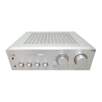
Detailed layout and identification of front panel controls and indicators.

Rear Panel Descriptions

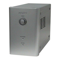
Identification of rear panel connectors and terminals for input/output.

Section 2 Electrical Adjustment

Bias Adjustment

Procedure for setting the bias voltage for optimal amplifier performance.

Adjustment Location

Visual guide indicating where to perform bias adjustment on the main board.

Section 3 Diagrams

Circuit Boards Location

Overview of the internal circuit board layout and their placement.

Schematic Diagram - Input Section

Electrical schematic detailing the input signal processing circuitry.

Printed Wiring Board - Input Section

Layout of the input section's printed circuit board traces and component placement.

Schematic Diagram - Main Section

Electrical schematic of the main amplifier circuitry, including power and output stages.

Printed Wiring Board - Main Section

Layout of the main section's printed circuit board, showing component placement.

Schematic Diagram - Panel Section

Electrical schematic for the front and rear panel controls and indicators.

Printed Wiring Board - Panel Section

Layout of the panel section's printed circuit board, detailing component placement.

Schematic Diagram - Power Section

Electrical schematic of the power supply and power amplifier stages.

Printed Wiring Board - Power Section

Layout of the power section's printed circuit board, showing component placement.

IC Block Diagrams

Functional block diagrams for integrated circuits used in the unit.

IC Pin Function

Detailed list of pin functions for specific integrated circuits.

Section 4 Exploded Views

Case Section Exploded View

Diagram showing the breakdown of the unit's outer casing and related parts.

Front Panel Section Exploded View

Detailed exploded view of the front panel components and their assembly.

Chassis Section Exploded View

Exploded view illustrating the internal chassis structure and component mounting.

Section 5 Electrical Parts List

HP Input Components

List of electrical parts for the Headphone input section.

Main Board Components

Comprehensive list of electrical parts for the Main board.

Outlet and Panel Components

Electrical parts list for Outlet and Panel sections of the device.

Phono and PS Board Components

List of electrical parts for the Phono and Power Supply boards.

S-D LED, SIRCS, SP-TM Components

Parts list for S-D LED, SIRCS, and SP-TM boards.

Tone and Volume Board Components

List of electrical parts for the Tone control and Volume boards.

Related product manuals