Do you have a question about the Sony TA-FB930R and is the answer not in the manual?
Details the electrical and performance characteristics of the amplifier section, including power output and distortion.
Lists general technical details such as power requirements, dimensions, and mass of the unit.
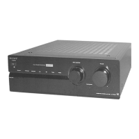
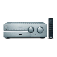
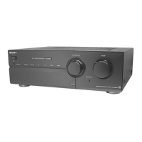
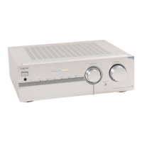
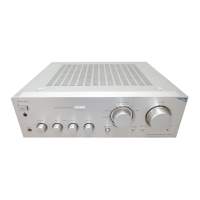
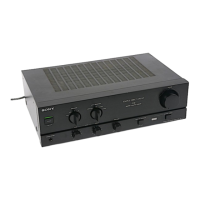
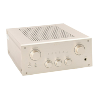
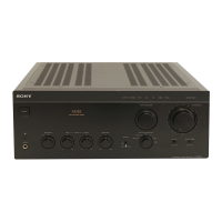
Identifies and describes controls and indicators on the front of the audio amplifier.
Procedure for adjusting bias on the main board, including location and required tools.
Illustrates the physical location of various circuit boards within the amplifier unit.
Provides the electrical schematic for the input section of the amplifier.
Electrical schematic for the main operational sections of the amplifier.
Electrical schematic for the front panel controls and indicators.
Electrical schematic for the power supply and output sections of the amplifier.
Illustrates IC block diagrams and details their pin assignments and functions.
Exploded diagram showing the assembly of the amplifier's case and external components.
Exploded diagram detailing the assembly of the front panel and its associated parts.
Exploded diagram illustrating the assembly of the internal chassis and major mechanical parts.
| Total Harmonic Distortion (THD) | 0.008% (at rated output) |
|---|---|
| Speaker load impedance | 4 - 16 ohms |
| Frequency Response | 5 Hz - 100 kHz |
| Signal-to-Noise Ratio | 105 dB |
| Input Impedance | 47 kΩ |
| Dimensions | 430 x 150 x 400 mm |
| Input sensitivity | 150 mV |
| Power Output | 100 W (4 ohms, 1 kHz, DIN) |
| Damping factor | 100 (8 ohms, 1 kHz) |