EasyManua.ls Logo

Sony TA-SB500WR2 User Manual

Sony TA-SB500WR2
30 pages
To Next Page IconTo Next Page
Page #1 background imageLoading...
Page #1 background image
SERVICE MANUAL
SURROUND AMPLIFIER
SPECIFICATIONS
TA-SB500WR2
Ver. 1.0 2007.03
9-887-591-01
2007C05-1
© 2007.03
Sony Corporation
Home Audio Division
Published by Sony Techno Create Corporation
US Model
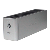
TA-SB500WR2 is the surround amplifier
section in DAV-HDX267W/HDX501W.
AUDIO POWER SPECIFICATIONS
POWER OUTPUT AND TOTAL HARMONIC
DISTORTION:
With 3 ohms loads, both
channels driven, from
120 Hz - 20,000 Hz; rated
60 watts per channel
minimum RMS power,
with no more than 0.7 %
total harmonic distortion
from 250 milli watts to
rated output.
Amplifier section
Surround mode (reference)RMS output power
SL/SR* : 100 W
(per channel at 3 ohms, 1
kHz, 10 % THD)
*Depending on the sound field setting and the source,
there may be no sound output.
Power requirements:
120 V AC, 60 Hz
Power consumption On: 40 W
Dimensions (approx.) 65 × 89 × 253 mm
(2
5
/
8
× 3
5
/
8
× 10 inches)
(w/h/d)
65 × 89 × 345 mm
(2
5
/
8
3 ×
5
/
8
× 13
5
/
8
inches)
(w/h/d) incl. speaker cord
cover
Mass (approx.) 1.3 kg (2 lb 14 oz)
1.4 kg (3 lb 2 oz) incl.
speaker cord cover
Design and specifications are subject to change
without notice.
Question and Answer IconNeed help?

Do you have a question about the Sony TA-SB500WR2 and is the answer not in the manual?

Sony TA-SB500WR2 Specifications

General IconGeneral
BrandSony
ModelTA-SB500WR2
CategoryAmplifier
LanguageEnglish

Summary

AUDIO POWER SPECIFICATIONS

SECTION 1 GENERAL

SECTION 2 DISASSEMBLY

DISASSEMBLY FLOW

Outlines the step-by-step procedure for disassembling the unit.

SECTION 3 DIAGRAMS

BLOCK DIAGRAM

Provides a high-level functional overview of the unit's internal circuitry.

SCHEMATIC DIAGRAM - DIAT AMP Section (1/4)

Presents the first part of the DIAT Amplifier circuit schematic.

SCHEMATIC DIAGRAM - DIAT AMP Section (2/4)

Presents the second part of the DIAT Amplifier circuit schematic.

SCHEMATIC DIAGRAM - DIAT AMP Section (3/4)

Presents the third part of the DIAT Amplifier circuit schematic.

SCHEMATIC DIAGRAM - DIAT AMP Section (4/4)

Presents the fourth part of the DIAT Amplifier circuit schematic.

SCHEMATIC DIAGRAM - POWER SUPPLY Section

Provides the circuit schematic for the Power Supply section.

IC Pin Function Description

Details the function of each pin for specific integrated circuits.

Related product manuals