EasyManua.ls Logo

Sony TC-377 Service Manual

Sony TC-377
38 pages
To Next Page IconTo Next Page
Page #1 background imageLoading...
Page #1 background image
Power
Requirements:
Power
Consumption:
Bias
Frequency:
Track
System:
.
Reel
Size:
Tape
Speed:
Frequency
Response:
19
cm/s
(71/2
ips):
s
ips):
9.5
cm/s
(33/4
ips):
19em/s
(74
19cm/s
(74/,
ips):
19
cm/s
(if,
ips):
9.5
cm/s
(3%
ips):
4.8
cm/s
(1%
ips):
Signal-to-Noise
Ratio:
Distortion:
Wow
and
Flutter:
SONY-00124
AEP
Model
_..
AUS
Model
USA
Model
STEREL
SPECIFICATIONS
AC
120V,
60Hz
(Canada,
USA)
AC
100V,
110V, 117V,
125V,
220V,
240V,
50/60
Hz
{E)
AC
110V,
127V,
220V,
240V,
50/60
Hz
(AEP,
AUS)
38W
(Canada,
USA)
48w
(AEP,
E,
AUS)
Approx.
160
kHz
Four
track
two
channel
stereo
and
mono
7"
maximum
19
cm/s
(71/2
ips)
9.5
cm/s
(35/4
ips)
48
cm/s
(17
ips)
SPECIAL
(SONY
SLH
tape)
NAB
.
DIN
20~30,000
Hz
30~24,000
Hz
30~25,000
Hz
+3dB
30~20,000Hz.—=—-—.—«c
40~16,000
Hz
NORMAL
(Standard
tape)
NAB
DIN
20~25,000
Hz
30~20,000
Hz
30~20,000
Hz
+3dB
.
30~17,000
Hz
40~
13,000
Hz
30~9,000
Hz
NORMAL
SPECIAL
52
dB
or
better
55
dB
or
better
1.2%
.
19
cm/s
(71/2
ips):
0.09%
(RMS)
weighted
9.5
em/s
(334
ips):
0.12%
(RMS)
weighted
4.8
cm/s
(17
ips):
0.17%
(RMS)
weighted
Inputs:
Two
MICROPHONE
inputs
Impedance:
fow
impedance
Maximum
sensitivity:
-72dB
(0.2
mV)
Two
LINE
!Nputs
Impedance:
100kQ
:
Maximum
sensitivity:
-22dB
(0.06V)
REC/PB
connector
(AEP,
E,
AUS)
Input
impedance:
3.8k2
Outputs:
Two
LINE
OUTputs
;
Load
impedance:
more
than
10kQ
Output
level:
OdB
(0.78
V)
with
100kQ
load
REC/PB
connector
(AEP,
E,
AUS)
Output
impedance:
3.3kQ
HEADPHONE
output
Load
impedance:
8%
Semiconductors:
23
transistors,
5
diodes
Record
Head:
RF140-2902
(7029/1
kHz)
Playback
Head:
PF
140-4202
(1k2/1
kHz)
Erase
Head:
£F18-2902A1
(1.6k0/160
kHz)
Motor:
1C-624H1
(induction
motor)
Dimensions:
418
(w)
x
210
(h)
x
392
(d)
mm
16Y>
(w)
x
85/16
(h)
x
15716
(d)
inches
Weight:
10.6kg,
23Ib
60z
(Canada,
USA)
11.5kg,
25
lb
6oz
(AEP,
E,
AUS)
"SERVICE
MANUAL

Other manuals for Sony TC-377

Question and Answer IconNeed help?

Do you have a question about the Sony TC-377 and is the answer not in the manual?

Sony TC-377 Specifications

General IconGeneral
BrandSony
ModelTC-377
CategoryMeasuring Instruments
LanguageEnglish

Summary

Sony TC-377 Specifications

Power and Electrical Specifications

Details power requirements, consumption, bias frequency, and electrical inputs/outputs.

Tape Handling and Performance Specifications

Covers tape speed, track system, frequency response, S/N ratio, distortion, and wow/flutter.

Component and Physical Specifications

Lists semiconductors, motor type, dimensions, and weight.

Outline and Disassembly Procedures

1-1. Block Diagram

High-level functional representation of the tape recorder's internal circuitry.

1-2. Major Parts Location

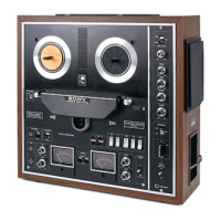
Visual identification of key external components and their positions.

1-3. Internal Views

Photographic views of the tape recorder's internal components and layout.

2-1. Cabinet Removal

Step-by-step guide for safely removing the tape recorder's outer cabinet.

Mechanical Adjustments

Tension, Pinch Roller, and Torque Adjustments

Adjusting tape tension, pinch roller pressure, stroke, and winding torques.

Other Mechanical Controls and Checks

Adjusting PAUSE, speed selector, shut-off, idler, and checking rollers.

Electrical Adjustments and Measurements

Tape Speed Calibration and Brake Checks

Calibrating tape speed and checking flywheel brake functionality.

Playback Head Adjustments and Calibration

Aligning playback head angle, azimuth, phase, curl, and output levels.

Record Head Alignment and Bias/Level Settings

Aligning record head, adjusting trap coils, bias, and record level for optimal recording.

Performance Measurements

Measuring dummy coils, erase ratio, distortion, frequency response, and S/N ratio.

Cross-talk and Input Level Checks

Measuring channel/track cross-talk and minimum input signal levels.

Power Frequency Adaptation

Power Frequency Adaptation

Instructions for adapting the motor for different line frequencies.

Diagrams

4-1. Level Diagrams

Diagrams illustrating signal levels within the playback and record circuits.

4-2. Schematic Diagram

Detailed electronic schematic of the tape recorder's circuitry.

4-3. Mounting Diagrams

Diagrams showing the physical placement of components on circuit boards.

Exploded Views and Packing

5-1. Cabinet - Top View

Exploded view showing assembly of the tape recorder's top cabinet section.

5-2. Head Deck - Top View

Exploded view detailing the assembly of the head deck mechanism.

5-3. Amplifier Chassis - Top View

Exploded view illustrating the components on the amplifier chassis.

5-4. Chassis - Top View

Exploded view showing the assembly of the main chassis.

5-5. Packing Instructions

Instructions and illustrations for packing the tape recorder for shipment.

Parts List and Hardware

Section 6: Electrical Parts List

Comprehensive list of electronic components with part numbers.

Section 7: Hardware

Lists and diagrams of screws, washers, nuts, retaining rings, and hardware identification.

Related product manuals