EasyManua.ls Logo

Sony TC-580 Service Manual

Sony TC-580
79 pages
To Next Page IconTo Next Page
Page #1 background imageLoading...
Page #1 background image
Power
Requirements:
Power
Consumption:
Track
System:
Reel
Size;
Tape
Speed:
Recording
Time:
(with
1,800
ft,
tape)
Frequency
Responsa:
Signal-to-Noise
Ratio:
Flutter
and
Wow:
AC
160
V,
110
V,
120
V,
127
V,
220
V
or
240
V
50/60
Hz
90W
4-track
stereophonic
and
monophonic
7”
(18
em)
maximum
7/2
ips,
3
344
ips,
1
7/8
ins
{19
cm/s,
9.6
cm/s,
4,8
cm/s)
Tape
speed
7 %
ips
(19
em/s}
1.5 bes
3%
ips
(9.5
cm/s)
Shrs
(with
SONY
SLH
tape}
20~
30,000
Hz
at
7
1/2
ips
(19
cm/s)
20~
20,000
Hz
at
3
3/4
ips
(9.5
cm/s}
(with
standard
tape)
20~
25,000
Hz
at
71/2
ips
(19
emis}
30~
17,000
Hz
at
3
3/4
ips
(9.5
cm/s}
30~
9,000
Hz
at
1
7/8
ips
(4.8
cm/s}
56
dB
(with
SLH
tape}
53
d8
(with
standard
tape)
0.06
%
at
7
1/2
ips
(19
om/s}
0.10
%
at
3.
3/4
ips
(9.5
cm/s)
0.20%
at
1
7/8
ips
(4.8
cm/s}
SPECIFICATIONS
4-track
stereo
4-track
mono
3hrs
6
hrs
Recording
Bias
Frequency:
Inputs:
Outputs:
‘Overalt
Distortion:
Semiconductors:
Dimensions:
Weight:
Approx.
160
kHz
,
Two
MIC
inputs
.
impedance:
Maximum
sensitivity:
Two
AUX
inputs
impedance:
Maximum
sensitivity:
REC/PB
connector
Impedance:
Input
level:
Two
LINE
Outputs
Load
impedance:
Output
level:
HEADPHONE
Output
Load
impedance:
Output
level:
1.2%
low
impedance
0.2
mV
(—72
cB}
100
kQ,
0.06
V
(~22
dB)
10kQ
17.4
mV
(33
dB)
100
k&2
0:775
V
(0
d8)
BQ
12.6
mV
(-36
dB)
at
1
of
level
switch
31
mV
{28
dB)
at
2
of
level
switch
45
transistors,
1
integrated
circuit,
27
diodes
17
ew)
x8
Ve
(446
x
225
x
460
mm)
43
tb
(19.5
kg}
(H}
x18
1/8"
(0)
ON
Ye
SERVICE
MANUAL
Question and Answer IconNeed help?

Do you have a question about the Sony TC-580 and is the answer not in the manual?

Sony TC-580 Specifications

General IconGeneral
BrandSony
ModelTC-580
CategoryMeasuring Instruments
LanguageEnglish

Summary

TC-580 Specifications

TC-580 General Description

TC-580 Block Diagram

Block diagram illustrating the main functional units and signal flow of the TC-580.

TC-580 Major Parts Locations

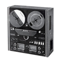
Identifies major components and their physical locations on the TC-580 unit.

TC-580 Switch Locations

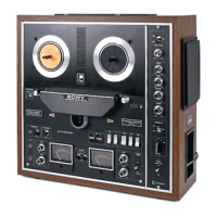
Illustrates the locations of various switches on the TC-580 control panel and chassis.

TC-580 Disassembly Procedures

TC-580 Cabinet Removal

Procedures and diagrams for removing the outer cabinet of the TC-580.

TC-580 Head Deck Removal

Steps and illustrations for removing the head deck assembly.

TC-580 Circuit Board Removal

Instructions for removing specific circuit boards like record equalizer and reverse switch.

TC-580 Adjustment Procedures

TC-580 Mechanical Adjustments

Detailed procedures for mechanical adjustments to ensure proper operation.

TC-580 Electrical Adjustments

Detailed procedures for electrical adjustments to ensure optimal performance.

TC-580 Post-Adjustment Checks

Verification checks for mechanical operations like torque, roller contact, and wow/flutter.

TC-580 Diagrams and Schematics

TC-580 Schematic Diagrams

Detailed schematic diagrams of the audio, bias, ESP, reverse, relay, power supply, and servo circuits.

TC-580 Mounting Diagrams

Diagrams showing the physical layout and mounting of circuit boards and components.

TC-580 Level Diagrams

Diagrams showing signal levels at various points in the playback and record circuits.

TC-580 Electrical Parts List

TC-580 Semiconductors, Coils, Transformers

Lists semiconductors, microinductors, coils, and transformers used in the TC-580 circuits.

TC-580 Capacitors and Resistors

Lists capacitors and resistors with their part numbers, values, and specifications.

TC-580 Switches, Jacks, Miscellaneous

Lists of switches, jacks, and other minor components like lamps and meters.

TC-580 Exploded Views

TC-580 Packing Exploded View

Exploded view and list of parts for packaging and unpacking the TC-580 unit.

TC-580 Cabinet Top View Exploded Diagram

TC-580 Cabinet Top View Details

Exploded view showing the top view of the cabinet and placement of various parts.

TC-580 Head Deck Top View Exploded Diagram

TC-580 Head Deck Top View Details

Exploded view illustrating the top view of the head deck assembly and its components.

TC-580 Amplifier Chassis Top View Exploded Diagram

TC-580 Amplifier Chassis Top View Details

Exploded view of the amplifier chassis showing the top-side component layout.

TC-580 Chassis Top View (1) Exploded Diagram

TC-580 Chassis Top View (1) Details

Exploded view of the chassis, showing top-side parts, first of two views.

TC-580 Chassis Top View (2) Exploded Diagram

TC-580 Chassis Top View (2) Details

Exploded view of the chassis, showing top-side parts, second of two views.

TC-580 Chassis Top View (3) Exploded Diagram

TC-580 Chassis Top View (3) Details

Exploded view of the chassis, showing top-side parts, third of three views.

TC-580 Chassis Bottom View Exploded Diagram

TC-580 Chassis Bottom View Details

Exploded view illustrating the bottom view of the chassis and its components.

TC-580 Service Manual Supplement

TC-580 Supplement: Circuit Description

Description of the main circuit operation, including record amp and muting circuits.

TC-580 System Control

TC-580 System Control: Tape Transport Direction

Explanation of how the tape transport direction is changed via solenoids and relays.

TC-580 ESP Circuit Operation

TC-580 ESP Operation: No Signal

Describes ESP circuit operation when no signal is detected at the start of playback.

TC-580 ESP Operation: Signal Detected

Describes ESP circuit operation when recorded signal is detected during forward playback.

TC-580 ESP Operation: Signal Ends

Explains ESP circuit behavior when recorded signal ends.

TC-580 ESP Operation: Post-Direction Change

Details how transistors and relays function after tape direction reversal.

TC-580 AC Servo Circuit

TC-580 AC Servo Circuit Principle

Explains the servo circuit's principle and how it maintains constant tape speed.

TC-580 Servo Amplifier Operation

Describes how the servo amplifier circuit operates by changing impedance R.

TC-580 Motor Speed Deviation Response

Details how the servo circuit reacts to and corrects motor speed deviations.

TC-580 Switch Operation Sequences

TC-580 Switch Sequence: FWD/REV

Outlines the sequence of switch operations for FWD and REV modes.

TC-580 Switch Sequence: FF/REW

Details the sequence of switch operations for FF and REW functions.

TC-580 Switch Sequence: Mode Transition

Describes the circuit logic for changing between FWD and REV playback modes.

Related product manuals