Do you have a question about the Sony TC-854-4 and is the answer not in the manual?
| Output | 0.775V (line) |
|---|---|
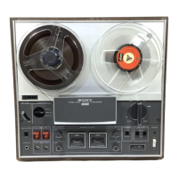
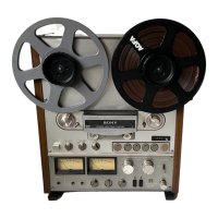
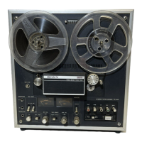
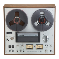
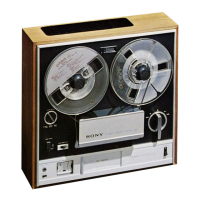
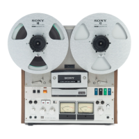
| Type | Reel to Reel |
| Track System | 4-track, 4-channel |
| Track Configuration | 4-track |
| Tape Speeds | 3¾ and 7½ ips |
| Heads | 2 x record, 2 x playback, 1 x erase |
| Wow and Flutter | 0.04% (7 1/2 ips) |
| Semiconductors | 48 x transistors, 37 x diodes |
Overview diagram of the tape recorder's functions.
Detailed technical specifications and system control aspects.
Explanation of the TC-854-4's system control mechanism.
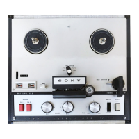
Identification of major components by location.
Identifies major parts on the front of the unit's cabinet.
Details the addition of the SYNC MONITOR AMP circuit.
Specifies serial numbers for which this supplement applies.
Procedure for removing the reel panel assembly.
Procedure for removing the amplifier panel.
Steps for removing the main unit cabinet.
Procedures for mechanical adjustments and calibration.
Steps for adjusting the unit's brake mechanism.
Procedure for calibrating brake torque for reels.
Adjusting reel tension and back tension.
Procedures for electrical calibration and performance checks.
Procedure to adjust playback head azimuth.
Adjusting the recording bias level.
Detailed schematic diagram of the amplifier section.
Component layout diagram for the playback amplifier.
Component layout diagram for the bias oscillator.
Schematic diagram of the mechanical chassis.
Exploded view of cabinet top components.
Exploded view of head deck components from top.
Exploded view of chassis top components (part 1).
List of capacitors with part numbers.
List of resistors with part numbers.
List of switches with part numbers and positions.
List of various screws used for assembly.
List of nuts used in the unit.
List of washers used in the unit.