Do you have a question about the Sony TC-FX211 and is the answer not in the manual?
Lists mechanical and other parts that differ from TC-FX170.
Covers recording system, signal-to-noise ratio, distortion, frequency response, and wow/flutter.
Details power requirements for different models and Dolby noise reduction information.
Information on how to identify the model number from the back panel label.
Outlines methods to check AC leakage for safety compliance.
Details mechanical adjustments, precautions, and torque specifications.
Covers procedures for electrical adjustments like record bias and level.
Shows the overall block diagram and signal flow within the device.
Illustrates the layout of components on the printed wiring boards.
Details head alignment and playback level adjustment procedures.
Provides detailed schematic diagrams for the audio, switch, and power supply boards.
Exploded view of the cabinet and front panel sections with part identification.
Exploded views of the tape mechanism sections for disassembly and parts identification.
Lists capacitors, semiconductors, coils, filters, and transistors with part numbers.
Lists resistors and variable resistors (potentiometers) with specifications.
Lists integrated circuits, transistors, and filters with part numbers.
Lists switches, connectors, transformers, and accessory items.
Lists screws, rings, and lugs used in the assembly.
| Track System | 4-track, 2-channel stereo |
|---|---|
| Tape Speed | 4.8 cm/s |
| Heads | 1 x record/playback, 1 x erase |
| Tape Type | type I, CrO2, Metal |
| Frequency Response | 30Hz to 15kHz (Metal tape) |
| Total Harmonic Distortion | 1.5% |
| Input | 70mV (line) |
| Output | 0.44V (line) |
| Frequency Response (Metal Tape) | 30Hz to 15kHz |
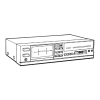
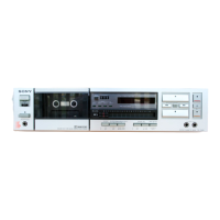
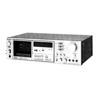
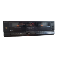
| Type | Cassette Deck |
| Motor | DC servo motor |
| Signal-to-Noise Ratio | 58 dB (Dolby B Off) |
| Dimensions | 430 x 110 x 250mm |
| Power Supply | 220V AC, 50Hz |
| Frequency Response (Normal Tape) | 30Hz to 13kHz |
| Signal-to-Noise Ratio (Dolby B On) | 64dB |
| Inputs | 1 x line |
| Outputs | Line Out, Headphone |