2/01-15_BVM-14M4DE 3-860-496-01 (1) (J/E)
14(E)
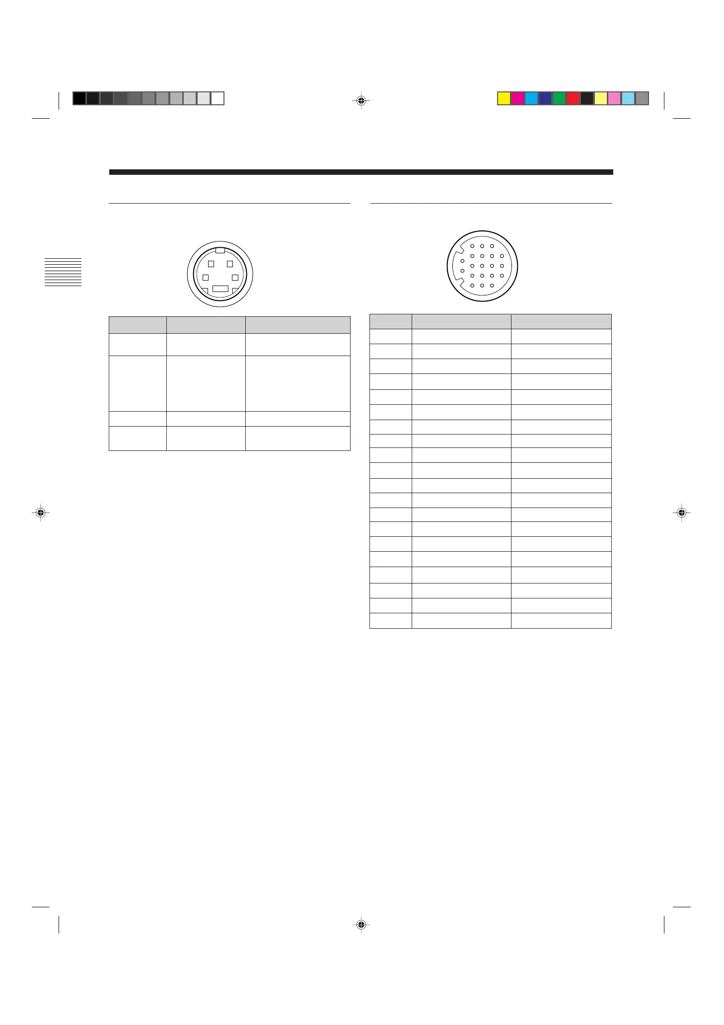
Pin assignment
Y/C IN connector (4-pin mini-DIN)
REMOTE connector (20-pin)
Signal
Blue only
H/V DELAY
MAIN/SUB*
EXT SYNC
DEGAUSS
R ch ON/OFF*
TALLY
LINE B
GND
GND
GND
GND
LINE A
LINE/RGB
GND
L ch ON/OFF*
REMOTE
LINE C
UNDER SCAN
16:9
Wire color
Brown
Red
Orange
Yellow
Green
Blue
Purple
Grey
White
Black
Pink
Light Blue
Spiral Orange
Spiral Yellow
Spiral Green
Spiral Blue
Spiral Purple
Spiral Grey
Spiral Pink
Spiral Light Blue
Pin No.
1
2
3
4
5
6
7
8
9
10
11
12
13
14
15
16
17
18
19
20
(* For digital audio control)
How to connect a remote control unit
Connect No.17 pin to one of the GND pins (No.9 – 12,
and 15), then connect pins for the functions you want
to use to other GND pins (No.9 – 12, and 15).
How to light the tally lamp
Connect No.7 pin to one of the GND pins (No.9 – 12,
and 15).
Signal
Y-input
CHROMA
subcarrier-input
GND for Y-input
GND for
CHROMA-input
Description
1 Vp-p, sync negative,
75 ohms
300m Vp-p (PAL)/286m
Vp-p (NTSC), burst
Delay time between Y
and C: within 0 ± 100
nsec., 75 ohms
GND
GND
Pin No.
1
2
3
4
3
1
2
4
5
6
7
8
9
10
11
12
13
14
15
16
17
18
19
20
21
34
*
Specifications