EasyManua.ls Logo

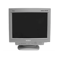
Sony Trinitron CPD-420GST User Manual

Sony Trinitron CPD-420GST
51 pages
To Next Page IconTo Next Page
Page #1 background imageLoading...
Page #1 background image
SPECIFICATIONS
Picture tube 0.25 - 0.27 mm aperture grill pitch
19 inches measured diagonally
90-degree deflection
Trinitron
Power Consumption
Maximum
Nominal
130 W
100 W
Video image area (18” maximum viewing image)
Approx. 365 x 274 mm (w/h)
(14
3/8
x 10
7/8
inches)
Deflection frequency Horizontal: 30 to 96 kHz
Vertical: 48 to 120 Hz
Resolution Horizontal: Max 1600 dots
Vertical: Max. 1200 lines
AC input voltage / current 100 to 120 V, 50/60 Hz, 1.7 A
220 to 240, 50/60 Hz, 1.2 A
Standard image area Approx. 352 x 264 mm (w/h)
(13
7/8
x 10
1/2
inches)
Dimensions 444 x 467 x 455 (w/h/d)
(17
1/2
x 18
1/2
x 18 inches)
Input Signal
Video
Sync
Analog RGB (75 ohms typical)
0.7 V
p-p
, Positive
External HD/VD, Composite
Polarity Free TTL
Video Composite (Sync on Green)
0.3 V
p-p
, Negative
Mass Approx. 26 kg (57 lb 5 oz)
Design and specifications are subject to change without notice.
MICROFILM
US Model
AEP Model
Chassis No. SCC-L20A-A
D98 CHASSIS
Canadian Model
Chassis No. SCC-L20D-A
CPD-420GS
CPD-420GST
Question and Answer IconNeed help?

Do you have a question about the Sony Trinitron CPD-420GST and is the answer not in the manual?

Sony Trinitron CPD-420GST Specifications

General IconGeneral
Display TechnologyCRT
Tube TypeTrinitron
Maximum Resolution1600 x 1200
Aspect Ratio4:3
Input ConnectorsD-sub 15-pin

Summary

Power Saving and Self-Diagnosis Features

Self-Diagnosis Function

Explanation of the self-diagnosis feature using the STANDBY/TIMER lamp for error indication.

Safety Checks and Warnings

Safety Check-Out Procedure

Steps to follow for safety checks after repair to ensure proper operation.

Leakage Test Procedure

Methodology for testing AC leakage current from exposed metal parts.

Safety-Related Component Warnings

Alerts regarding critical components and procedures for safe operation.

Monitor Setup and Configuration

Connecting to Your Computer

Steps for connecting IBM PC/AT, Macintosh, or laptop computers via video cables.

Picture Adjustment Procedures

Monitor Maintenance and Troubleshooting

Resetting Adjustments and Technical Features

Methods for resetting adjustments and overview of technical features like Multiscan.

Troubleshooting Common Issues

Guidance for resolving display problems like no picture, fuzzy images, or color issues.

Detailed Troubleshooting Guide

Resolving 'No Picture' and Signal Issues

Solutions for blank screens, 'NO INPUT SIGNAL', and 'OUT OF SCAN RANGE' errors.

Addressing Picture Instability and Distortion

Fixes for flickering, scrambling, fuzzy, or ghosting picture problems.

Self-Diagnosis and Power Indicator Interpretation

Disassembly and Board Access

Picture Tube Removal and Handling

Picture Tube Assembly Removal

Detailed steps for safely removing the picture tube assembly from the monitor.

Anode Cap Removal and Handling

Procedure for removing the anode cap and guidelines for safe handling.

Safety Related Adjustment Procedures

HV Regulator and Hold-Down Checks

Verifying and adjusting the HV regulator and hold-down circuits for safety.

Beam Protector and B+ Max Checks

Testing the beam protector and verifying B+ voltage levels.

Monitor Adjustment Procedures

Landing and Convergence Rough Adjustments

Initial raster alignment and coarse convergence adjustments using magnets.

Fine Landing and Convergence Adjustments

Detailed steps for fine-tuning landing and convergence using specialized tools.

Advanced Convergence and Focus Adjustments

Six-Pole Magnet and Focus Adjustments

Adjusting HMC/VMC with six-pole magnets and optimizing picture focus.

Digital Convergence Adjustment Steps

Step-by-step guide for performing digital convergence adjustments using specific registers.

Circuit Diagrams and Component Locations

Schematic Diagrams and Printed Wiring Boards

Detailed schematics and wiring layouts for the monitor's main circuit boards.

N Board Schematics and Data

A Board Schematics and Data

D Board Schematics and Data

H Board Schematics and Data

Electrical Parts List

Service Manual Correction Notice

Digital Convergence Adjustment Correction

Instructions to correct the service manual regarding digital convergence adjustment.

Digital Convergence Adjustment Procedure

Step 1: H-STAT, V-STAT, HMC, VMC Adjustments

Adjusting H-STAT, V-STAT with 4-poles magnet and HMC/VMC with 6-poles magnet.

Step 2: H-TILT and XCV Correction

Correcting H-TILT with TLH plate and XCV with XCV core.

Step 3: Static Convergence Adjustment

Adjusting static convergence parameters (X_STATIC_CONV, Y_STATIC_CONV).

Steps 4-8: Dynamic Convergence Adjustments

Performing dynamic convergence adjustments using specific registers (03-83, 01-81, 05-85, 02-82, 04-84).

Related product manuals