— 26 —
KV-27FV16/29FV16/29FV16C/32FS12/32FS16
5-4. MA BOARD ADJUSTMENTS
H. Frequency (Free Run) Check
1. Input a TV mode (RF) with no signal.
2. Connect a frequency counter to base of Q501
(TP-500 H. DRIVE) on the A Board.
3. Check H. Frequency for 15735 ± 200 Hz
V. Frequency (Free Run) Check
1. Select video 1 with no signal input.
2. Set the conditions for a standard setting.
3. Connect the frequency counter to TP-508 (V OUT) or
CN501pin
(V DY+) and ground on the A Board .
4. Check that V. Frequency shows 60 ± 4 Hz.
Drive (RDRV)
1. Input a color-bar signal and set the level to 75%.
2. In Standard mode, set PICTURE to maximum and COLOR
to minimum.
3. Activate the Service Adjustment Mode.
4. Set both GON and BON items. Using
and ; set each to
the following values. Leave RON set to “1”.
SERVICE RON 1
1: ON
0: OFF
R ON: ON (1)
G ON: OFF (0)
B ON: OFF (0)
5. Connect an oscilloscope probe to CA Board, J701 Pin 12
(KR) (Red Out) .
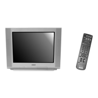
6. Select RDRV with
and .
7. Adjust the value of RDRV with
and for
92.5 ± 3 VDC.
8. Reset GON and BON values to “1”.
R ON: ON (1)
G ON: ON (1)
B ON: ON (1)
9. Reset Picture and Color to normal values:
PICTURE: MAX
COLOR: CENTER
10.Press
then to save into the memory.
Display Position Adjustment (DISP)
1. Input a color-bar signal.
2. Set to Service Adjustment Mode.
3. Select DISP with
and .
4. Adjust values of DISP with
and to adjust characters
to the center.
5. Write to memory by pressing
then .
6. Check to see if the text is displayed on the screen.
Sub Bright Adjustment (SBRT)
1. Input a monoscope signal.
2. Activate the Service Adjustment Mode.
3. Set the PICTURE and BRIGHTNESS to minimum.
4. Select the SBRT item with and .
5. Adjust the values of SBRT with
and to obtain a faintly
visible crosshatch.
6. Press
then to save into the memory.
Sub Hue, Sub Color Adjustment (CHUE, CCOL)
1. Input a color-bar signal and set level to 75%.
2. Activate the Service Adjustment Mode.
3. Connect an oscilloscope probe to CA Board, CN705
Pin
.
4. Select the CHUE and CCOL item with
and .
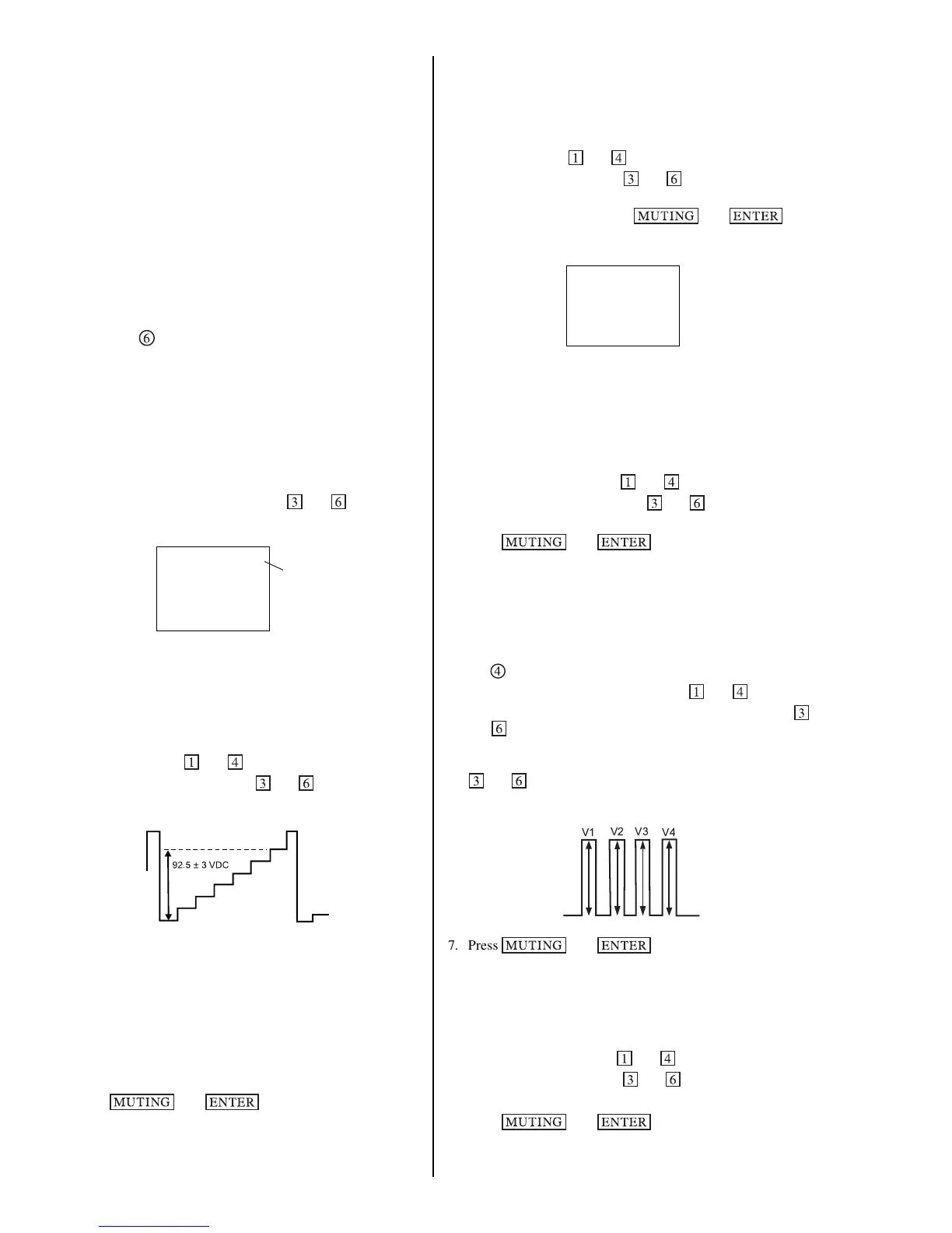
5. While showing the CHUE item, adjust the waveform with
and until the second and third bars show the same level
(V2 = V3 < 0.1 Vp-p).
6. While showing the CCOL item, adjust the waveform with
and until the first and fourth bars show the same level
(V1 = V4 < 0.1 Vp-p).
V1
V2 V3
V4
7. Press then to save into the memory.
V. Size Adjustment (VSIZ)
1. Input a crosshatch signal.
2. Activate the Service Adjustment Mode.
3. Select the VSIZ item with
and .
4. Adjust value of VPOS with
and for the best vertical
center.
5. Press
then to save into the memory.