Do you have a question about the Sony TRINITRON KV-M1450A and is the answer not in the manual?
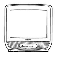
Details about the screen technology and size.
Lists the available input and output connections.
Details on power, dimensions, and weight of the remote.
Crucial safety advice for specific models regarding plugs and fuses.
Details each pin's function, signal type, and level.
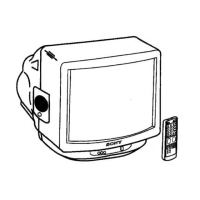
Initial steps for setting up and using the TV and remote.
Explains how to operate the TV using the remote and on-set controls.
Step-by-step guide for manual channel tuning and storage.
Instructions on how to access and view teletext information.
Explains features like superimposing and freezing teletext pages.
How to navigate the TV's menu system for adjustments.
How to configure the TV to turn off automatically.
How to skip unused channel memory slots.
Guide to fine-tune the frequency of stored TV channels.
Details on connecting external audio/video equipment via the 21-pin port.
Instructions for plugging in headphones and how sound is affected.
Solutions for picture and sound issues, remote control problems.
Step-by-step guide to remove the rear casing of the TV.
How to position the TV for internal servicing.
Procedure for safely removing the CRT picture tube.
Specific instructions for safely removing and handling the anode cap.
Steps before starting adjustments, including degaussing.
How to adjust the electron beam for optimal convergence.
Procedures for adjusting horizontal and vertical static convergence.
Adjusting convergence during dynamic picture display.
Adjusting convergence at the edges of the screen.
Detailed procedures for screen, drive, white balance, and color settings.
How to adjust the focus control for the sharpest picture.
Performing electrical adjustments using the remote control and on-screen menu.
Description of various test modes available for diagnostics and calibration.
Procedures for IF signal adjustment and System L tuning.
Steps for AGC adjustment and deflection system calibration.
Using diagnostic software to identify chassis errors via LED flashes.
High-level diagram showing the main functional blocks of the TV.
Identifies the physical location of key circuit boards.
Visual representation of circuit schematics and printed wiring boards.
Displays reference waveforms for signal analysis on the A Board.
Details on IC101, IC301, and IC601 found on the A Board.
Identifies ICs and diodes on the C Board.
Visual layout showing general placement of components on the A Board.
Identifies ICs and diodes on the C Board.
Identifies ICs, transistors, and diodes on the A Board.
Lists resistors on the A Board with their values and ratings.
Exploded view showing chassis components and the picture tube assembly.
List of capacitors, coils, and resistors with part numbers and specifications.
Detailed list of capacitors for A and C boards.
List of diodes and other components for A and C boards.
Parts list for inductors, transistors, and integrated circuits on A and C boards.
Detailed list of resistors for A and C boards.
Continued list of resistors for A and C boards.
List of resistors, fuses, and ferrite beads for A and C boards.
List of capacitors and diodes for A and CC boards.
Listing of antennas, power cords, and protective bags.
Includes cushions, cartons, and instruction manuals for various models.
Details about the standard remote commander (RM-836).
Detailed list of resistors for A and C boards.
List of transistors, fuses, and ferrite beads for A and C boards.
Lists high voltage capacitors and power cords.
Details about TV tuners and the picture tube.
Lists antennas, protection bags, and cushions.
| Screen Size | 14 inches |
|---|---|
| Display Type | CRT |
| Aspect Ratio | 4:3 |
| Brand | Sony |
| Model | KV-M1450A |
| Inputs | RF |