Do you have a question about the Sony TRINITRON KV-M1450B and is the answer not in the manual?
Lists all KV-M1450/KV-M1451 models with destination and chassis numbers.
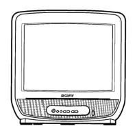
Details picture tube, power consumption, and input/output terminals.
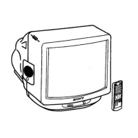
Instructions for inserting batteries into the remote commander.
Guides for connecting aerials and VCRs to the TV set.
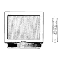
Covers automatic channel preset, basic TV operation, and Teletext.
Adjusting picture, using Teletext, and setting the sleep timer.
Skipping programme positions, fine-tuning, and exchanging positions.
Using headphones and the 21-pin connector for external devices.
Steps for rear cover removal, service position, and picture tube removal.
Procedures for beam landing, convergence, focus, and white balance.
Electrical, test mode, IF, AGC, and deflection system adjustments.
Software for error identification and reporting within the BE-4 chassis.
Overview of the TV's functional blocks and signal flow.
Location of circuit boards and detailed schematic diagrams.
Visual breakdown of parts, chassis, and a comprehensive electrical parts list.
Details part number updates for specific models and serial numbers.
| Screen Size | 14 inches |
|---|---|
| Display Type | CRT |
| Aspect Ratio | 4:3 |
| Brand | Sony |
| Model | KV-M1450B |
| Audio Output Mode | Mono |
| Type | Television |
| Inputs | Composite, RF |