Do you have a question about the Sony TRINITRON KV-M1400K and is the answer not in the manual?
Instructions for turning the TV on and off using the unit and remote.
Procedure for automatically presetting TV channels using the remote commander.
How to select programs, adjust volume, and fine-tune channels and picture.
Guide to viewing teletext, using advanced features, and FASTEXT.
Connecting external devices like VTR, cameras, and using video input.
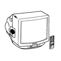
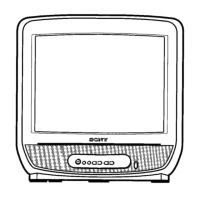
Overview of buttons, controls, and their functions.
Solutions for common picture, sound, and remote control problems.
Step-by-step guide to remove the rear cover of the TV.
Instructions for removing the V board, specific to KV-M1401 models.
Guidance on placing the unit in a service position for maintenance.
Procedure for safely removing the picture tube, including anode-cap handling.
Adjusting beam landing using a degausser and pattern generator.
Detailed steps for horizontal, vertical, dynamic, and screen-corner convergence adjustments.
Procedure for adjusting the picture focus for optimal sharpness.
Setting the screen (G2) and adjusting white balance for accurate color reproduction.
Circuit adjustments for the A board specific to M1400D/M1401D/M1400B models.
Circuit adjustments for the A board specific to M1400K/M1401K models.
Circuit adjustments for the A board specific to M1400U/M1401U/M1400L/M1400A/M1400E.
Circuit adjustment for the V board, applicable only to M1401 models.
Diagram showing the location of major circuit boards within the TV.
Includes A board schematics, printed wiring boards, and waveforms.
Illustrations and part numbers for various semiconductor components used.
Exploded view of the chassis assembly with part numbers.
List of connectors, capacitors, filters, and ICs with part numbers.
List of diodes, fuses, and coils with part numbers.
List of transistors and resistors with part numbers.
List of variable resistors, crystals, switches, transformers, and tuners.
| Screen Size | 14 inches |
|---|---|
| Display Type | CRT |
| Aspect Ratio | 4:3 |
| Tuner | Analog |
| TV System | PAL |
| Power Source | AC 220-240V |
| Inputs | RF, Composite |