EasyManua.ls Logo

Sony TRINITRON KV-M2140B User Manual

Sony TRINITRON KV-M2140B
48 pages
To Next Page IconTo Next Page
Page #1 background imageLoading...
Page #1 background image
KV-M2140B
SERVICE
MANUAL
(KV-M2140B
}
Television
system
Color
system
Channel
coverage
Picture
tube
Inputs
Outputs
Sound
output
Eaaee
MICROFILM
KV-M2140B
RM-694
French
Model
Chassis
No.
SCC-E24C-A
BE-2A
cuassis
MODELS
OF
THE
SAME
SERIES
KV-M1620B
KV-M1420B
SPECIFICATIONS
Power
consumption
B/G/H/L
Dimensions
PAL/SECAM
Weight
B/G/H
VHF
:
E2-E12
(RM-694)
UHF
:
E21-E69
Remote
control
system
CABLE
TV:
S1-S20
Power
requirements
L
VHF:
02-10,
B-Q
UHF
:
F21-F69
Dimensions
Black
Trinitron
tube
Weight
90°
degree
deflection
Accessories
supplied
Approx.
54.5
cm
(21
inches)
(Approx.51.0cm
picture
measured
diagonally)
Supplied
accessories
21-pin
connector
:
CENELEC
standard
Including
RGB
input
Audio/Video
input
jacks:
phono
jacks
70.5
Wh
Approx.
513x475x487
mm
(w/h/d)
Approx.
24.9
kg
infrared
control
3V
de
2
batteries
IEC
designation
R6
(size
AA)
Approx.
55
X18
X
185mm
(w/h/d)
Approx.
100g
including
batteries
IEC
designation
R6
batters
(2)
RM-694
Remote
Commander
(1)
IEC
designation
R6
batteries
(2)
S-Video
input
Design
and
specifications
are
subject
to
change
without
21-pin
connector
:
CENELEC
standard
nptee:
Headphones
jack
:
minijack
5
W
(Music)
TRINITRON»
COLOR
TV
SONT'Y.
Question and Answer IconNeed help?

Do you have a question about the Sony TRINITRON KV-M2140B and is the answer not in the manual?

Sony TRINITRON KV-M2140B Specifications

General IconGeneral
Screen Size21 inches
Display TypeCRT
Aspect Ratio4:3
BrandSony
ModelKV-M2140B
TV TypeStandard Definition
TunerAnalog
InputsComposite, RF

Summary

Section 1 General

1-1. Index of the Parts

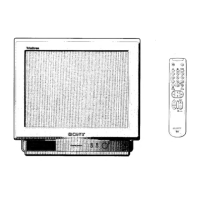
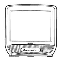
Lists parts and their functions on the set or remote commander.

1-2. To Preset Channels

Describes how to preset TV channels using the remote commander.

1-3. Daily Use of the TV

Basic operation of the TV using the remote commander and set buttons.

1-4. Picture and Sound Adjustments

Explains how to adjust volume, picture settings, and mute sound.

Section 2 Disassembly

2-1. Rear Cover Removal

Instructions for removing the rear cover of the TV set.

2-2. Service Position

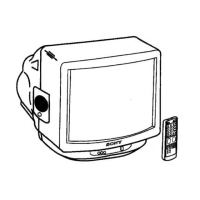
Describes how to place the TV in a service position for easier access.

2-3. Picture Tube Removal

Step-by-step guide for removing the CRT picture tube.

Section 3 Set-Up Adjustments

3-1. Beam Landing

Adjusting beam landing for proper picture alignment.

3-2. Convergence

How to adjust horizontal and vertical convergence for color alignment.

3-3. Focus

Adjusting the focus control for a sharp picture.

3-4. Screen (G2) and White Balance

Setting screen brightness and white balance for picture quality.

Section 4 Circuit Adjustments

4-1. A Board Adjustments

Specific adjustments for the A board, including AGC, H.FREQ, and more.

4-2. V Board Adjustment (KV-M2141K only)

Adjustments for the V board, focusing on RGB levels.

Section 5 Diagrams

5-1. Circuit Boards Location

Identifies the location of circuit boards within the TV chassis.

5-2. Schematic Diagrams and Printed Wiring Boards

Detailed schematics and printed wiring boards for the TV.

5-3. Semiconductors

Lists and illustrates various semiconductor components used in the TV.

Section 6 Exploded View

Exploded View

Visual breakdown of the TV components with reference numbers.

Section 7 Electrical Parts List

Electrical Parts List

Comprehensive list of electrical parts with part numbers.

Related product manuals