5
LINE A LINE B RGB ENTER
MENU/
EXIT
POWER
LINE A LINE B RGB ENTER
MENU/
EXIT
POWER
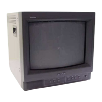
Location and Function of Parts and Controls
Front
1
Speaker
2
LINE A/LINE B/RGB buttons
3
MENU buttons
4
UPOWER
switch and
indicator
1 Speaker
2 LINE A/LINE B/RGB (input select) buttons
Press to select the program to be monitored.
Input signal
Signal fed through the LINE A connector
Signal fed through the LINE B connector
Signal fed through the RGB connectors
a)
a) Provided with the PVM-14N6A/14N6E/14N6U/20N6A/
20N6E/20N6U only.
Press
LINE A
LINE B
RGB
a)
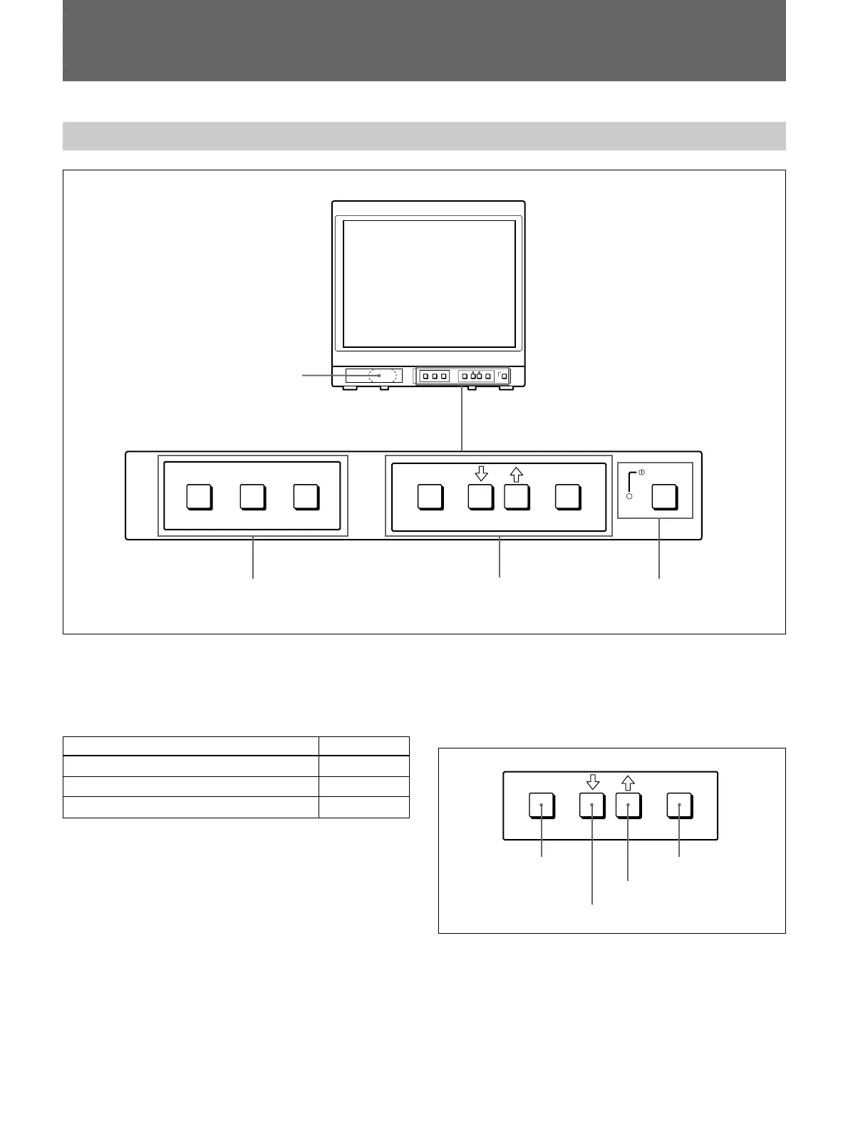
3 MENU buttons
Press to make the menu appear.
For detailed information on MENU buttons, see “Operation
through On-Screen Menus” on page 9.
4 UPOWER switch and indicator
Press to turn the monitor on. The indicator lights in
green.
To turn the power off, press this again.
ENTER
MENU/
EXIT
MENU/EXIT button
. button
> button
ENTER button