1
VPL-PX35/PX40
Table of Contents
1. Service Information
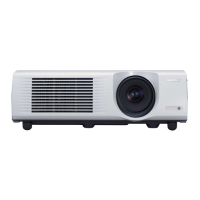
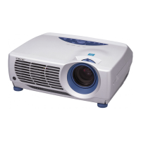
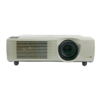
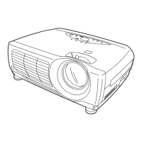
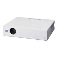
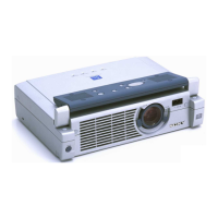
1-1. Appearance Figure ......................................................................................1-1
1-2. Board Locations ..........................................................................................1-1
1-3. Disassembly ................................................................................................ 1-2
1-3-1. Top Cover Assy and Hood Assy Removal ................................1-2
1-3-2. Projection Lens Removal ...........................................................1-3
1-3-3. C Board Removal .......................................................................1-3
1-3-4. NR Board Removal ....................................................................1-4
1-3-5. Side Panel Block Assy and Q Board Removal ..........................1-5
1-3-6. Bracket 92 and DC Fan 1 Removal............................................1-6
1-3-7. GA Board, GB Board and Bracket (G) Removal.......................1-6
1-3-8. OPT UNIT Assy and Lamp Box Removal ................................1-7
1-3-9. Prism Block Assy Removal .......................................................1-7
1-3-10. Bracket (BS), DC Fan 2 and Fan 1 Removal .............................1-8
1-3-11. Lamp Power Supply Block and V Board Removal ...................1-9
1-3-12. Fan 2 and U Board Removal ...................................................... 1-9
1-3-13. F Board Removal .....................................................................1-10
1-3-14. DC Fan 3 Removal................................................................... 1-10
1-4. Extension Boards and Extension Cables ................................................... 1-11
1-4-1. Connection ...............................................................................1-12
1-5. Warning on Power Connection .................................................................1-12
2. Electrical Adjustments
2-1. Preparation ..................................................................................................2-1
2-1-1. Required Equipment...................................................................2-1
2-1-2. How to Enter the Factory Mode .................................................2-1
2-2. V COM Adjustment ....................................................................................2-1
2-3. Initial Values of Adjustment Items .............................................................2-2
2-4. Service Know-How .....................................................................................2-9
2-4-1. When the Prism Block Is Replaced............................................2-9
2-4-2. When the C Board Is Replaced ..................................................2-9
2-5. White Balance Adjustment .........................................................................2-9
2-5-1. HIGH Mode of INPUT-D ..........................................................2-9
2-5-2. LOW Mode of INPUT-D .........................................................2-10
2-5-3. HIGH Mode of VIDEO............................................................2-10
2-5-4. LOW Mode of VIDEO.............................................................2-10
2-6. Memory Structure ..................................................................................... 2-11
3. Semiconductors................................................................................. 3-1
 Loading...