WM-EX678
— 19 — — 20 — — 21 —
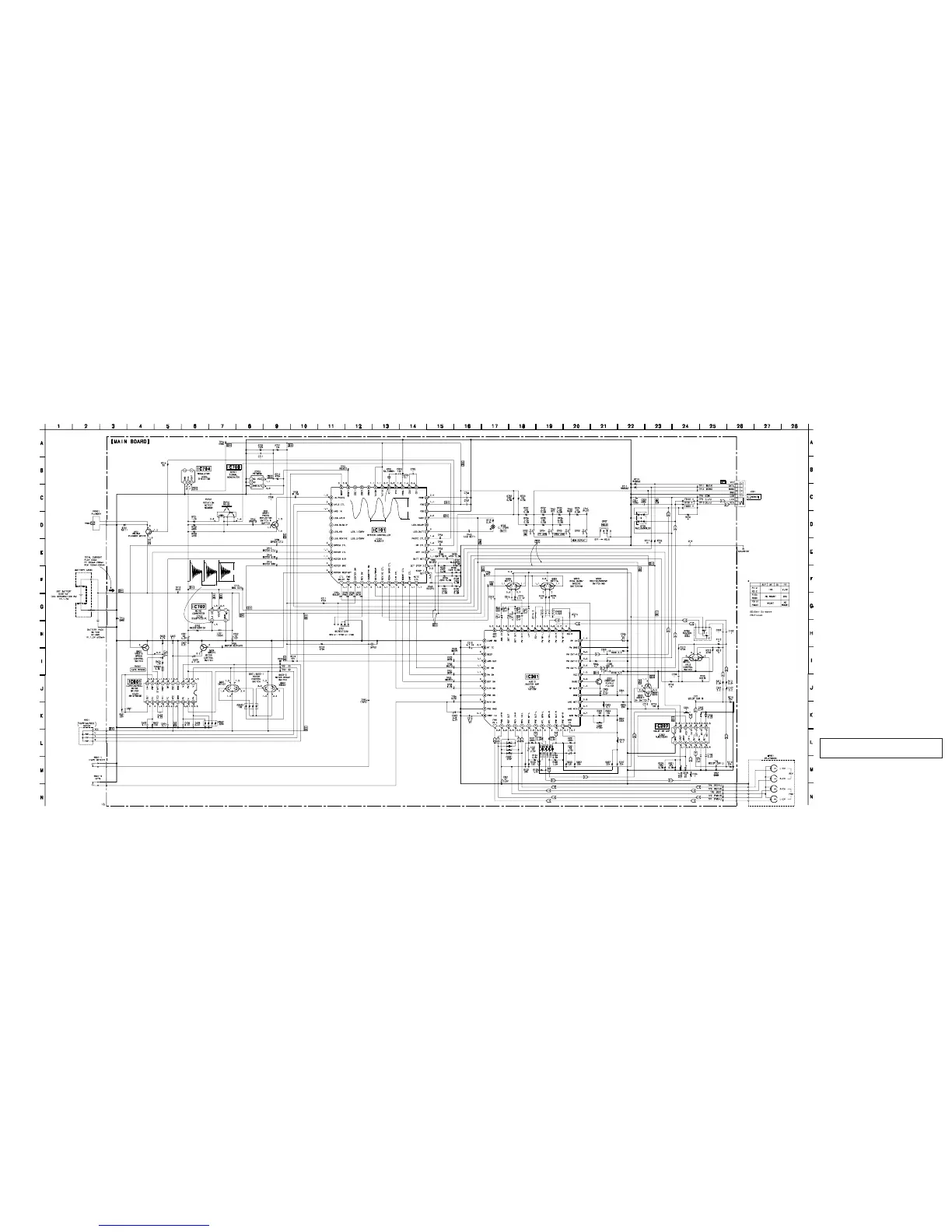
6-4. SCHEMATIC DIAGRAM
Note on Schematic Diagram:
• All capacitors are in µF unless otherwise noted. pF: µµF
50 WV or less are not indicated except for electrolytics
and tantalums.
• % : indicates tolerance.
• C : panel designation.
• U : B+ Line.
• H : adjustment for repair.
• Power voltage is dc 1.5V and fed with regulated dc power
supply from battery terminal.
no mark : PB
• Waveforms are taken with a oscilloscope.
Voltage variations may be noted due to normal produc-
tion tolerances.
• Signal path.
E : PB
• Abbreviation
FR : French
EE : East European
Note: The components identified by mark ! or dotted line
with mark ! are critical for safety.
Replace only with part number specified.
1.3 Vp-p
30.5 µsec
2.8 Vp-p
11 µsec
 Loading...