Do you have a question about the Sony XM-7547 and is the answer not in the manual?
Details power output and harmonic distortion levels for various channels and impedances per Car Audio Ad Hoc Committee standards.
Lists circuit system, inputs, speaker impedance, maximum outputs, rated outputs, frequency response, harmonic distortion, and input level range.
Instructions for clearing OVER CURRENT and OFF SET protectors by cutting jumper wires.
Details various speaker connection configurations and impedance notes.
Lists key features like maximum power output, bridging capability, and variable filters.
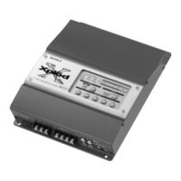
Detailed explanation of each control and indicator on the amplifier.
Procedures for adjusting idling current in HI-VOLTAGE mode using semi-fixed resistors.
Block diagram illustrating the signal flow within the amplifier section.
Block diagram of the power board, showing functional blocks and connections.
Schematic diagram for the amplifier board (part 1/3), showing circuit details.
Schematic diagram for the filter board, detailing its circuitry.
Printed wiring board layout for the amplifier section, showing component placement.
Schematic diagram for the amplifier board (part 2/3), detailing circuit components and connections.
Schematic diagram for the amplifier board (part 3/3), showing final circuit details.
Schematic diagram for the power board, illustrating its circuitry.
Printed wiring board layout for the power board (Side A), showing component placement.
List of electrical parts for the amplifier board, including part numbers and specifications.
| Brand | Sony |
|---|---|
| Model | XM-7547 |
| Category | Car Amplifier |
| Language | English |