– 10 –
SECTION 3
MECHANICAL ADJUSTMENTS
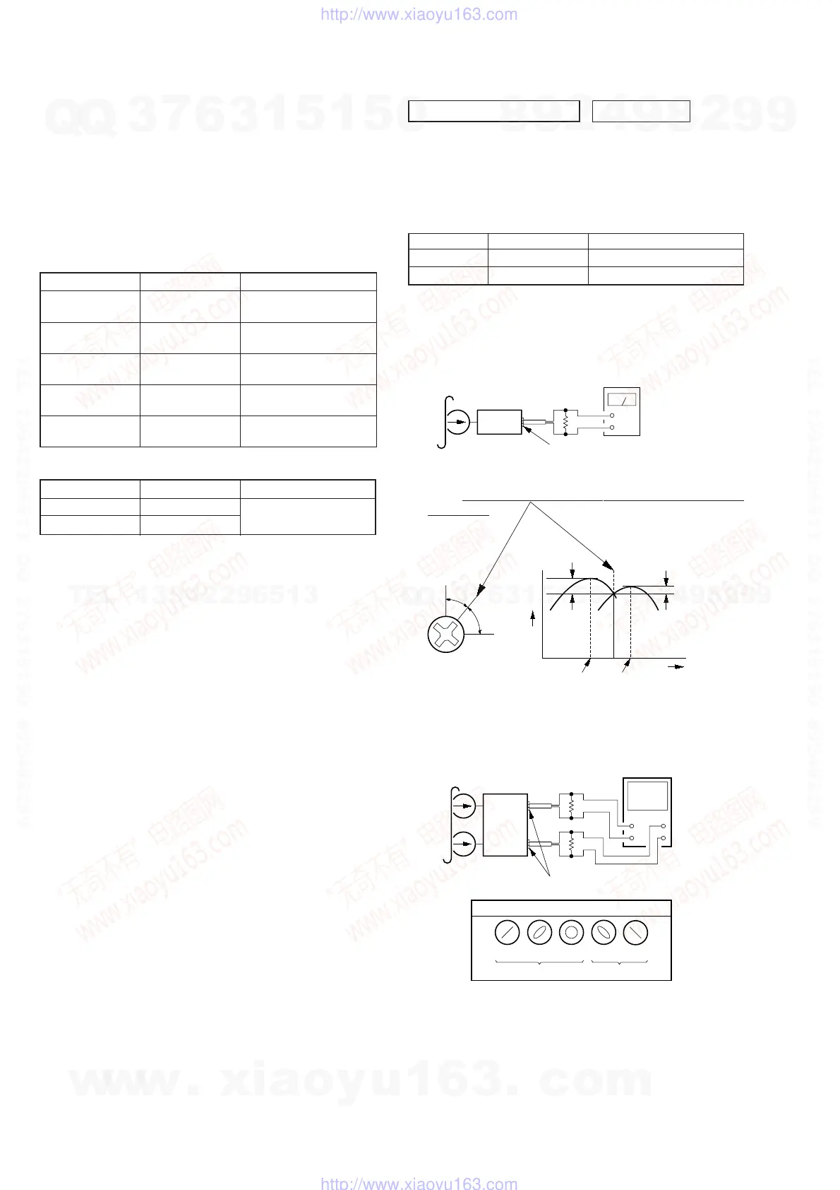
Mode Tension Meter Meter Reading
Forward CQ-403A more than 60 g
Reverse CQ-403R (more than 2.12 oz)
• Tape Tension Measurement
1. Clean the following parts with a denatured-alcohol-moistened
swab:
playback head pinch roller
rubber belt capstan
idler
2. Demagnetize the playback head with a head demagnetizer.
3. Do not use a magnetized screwdriver for the adjustments.
4. The adjustments should be performed with the power supply
voltage (14.4 V) unless otherwise noted.
• Torque Measurement
Mode Torque Meter Meter Reading
Forward CQ-102C
25 – 55 g•cm
(0.35 – 0.76 oz•inch)
Forward
CQ-102C
1.5 – 4 g•cm
Back Tension (0.02 – 0.06 oz•inch)
Reverse CQ-102RC
25 – 55 g•cm
(0.35 – 0.76 oz•inch)
Reverse
CQ-102RC
1.5 – 4 g•cm
Back Tension (0.02 – 0.06 oz•inch)
FF, REW CQ-201B
50 – 150 g•cm
(0.69 – 2.08 oz•inch)
SECTION 4
ELECTRICAL ADJUSTMENTS
TAPE DECK SECTION 0 dB= 0.775 V
1. The adjustments should be performed in the order given in
this service manual.
2. The adjustments should be performed for both L-CH and
R-CH.
Test Tape
PB Head Azimuth Adjustment
Procedure:
1. Put the set into the FWD PB mode.
2. Turn the screw and check the output peak value. Adjust the
screw
so that the peak value in channels L and R coincides
within 2 dB.
3. Check the phase in the FWD PB mode.
Type Signal Used for
P-4-A063 6.3 kHz, –10 dB head azimuth adjustment
WS-48A 3 kHz, 0 dB tape speed adjustment
screw
position
L-CH
peak
within
2 dB
output
level
L-CH
peak
R-CH
peak
within
2 dB
angl
R-CH
peak
test tape
P-4-A063
(6.3 kHz, –10 dB)
L-CH
R-CH
speaker out terminal
oscilloscope
V
H
+
+
–
–
Screen pattern
in phase
good wrong
45
°
90
°
135
°
180
°
4
Ω
4
Ω
set
level
meter
test tape
P-4-A063
(6.3 kHz, –10 dB)
set
speaker out termina
4
Ω
+
–
w
w
w
.
x
i
a
o
y
u
1
6
3
.
c
o
m
Q
Q
3
7
6
3
1
5
1
5
0
9
9
2
8
9
4
2
9
8
T
E
L
1
3
9
4
2
2
9
6
5
1
3
9
9
2
8
9
4
2
9
8
0
5
1
5
1
3
6
7
3
Q
Q
TEL 13942296513 QQ 376315150 892498299
TEL 13942296513 QQ 376315150 892498299
http://www.xiaoyu163.com
http://www.xiaoyu163.com
 Loading...