Do you have a question about the Sophos CS110-24 and is the answer not in the manual?
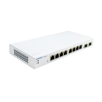
Diagram illustrating operating elements and connections for CS101-8x models.
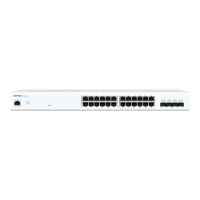
Diagram illustrating operating elements and connections for CS110-xx models.
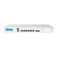
Diagram illustrating operating elements and connections for CS210-8FP models.
Diagram illustrating operating elements and connections for CS210-24/48FP models.
Details on COM and Reset interfaces and LED Mode button.
Connection details for the serial console RJ45 COM port.
How to reset the switch to factory default settings.
Function of the LED Mode button for PoE models.
Description of Power, Fault, PoE Max, LAN Mode, and PoE Mode LEDs.
Details on Speed and Link/Activity LEDs for RJ45 ports.
LED status for CS101-xx model RJ45 ports.
LED status for CS110/CS210 1G RJ45 ports.
LED status for CS210 2.5G RJ45 ports.
LED status for CS101-8FP PoE mode indication.
LED status for CS110/CS210 PoE mode indication.
Details on Link/Activity and Speed LEDs for SFP/SFP+ ports.
LED status for CS110/CS210 SFP/SFP+ ports.
Details of supplied parts as indicated in the Quick Start Guide.
General guidance for mounting the switch.
Important safety notes for operating the switch.
Safety measures and stability considerations for rack mounting.
General safety precautions for server installation in racks.
Step-by-step guide to attaching rack-mount ears to the switch.
Instructions for attaching brackets to the left and right sides of the switch.
Information on using SFP/SFP+ ports with transceivers or DAC cables.
Caution regarding laser safety for SFP/SFP+ ports.
Procedure for installing a SFP/SFP+ module into the switch port.
Procedure for removing a SFP/SFP+ module from the switch port.
Steps and settings for connecting to the serial console via RJ45 port.
| Uplink Ports | 4x 1G SFP |
|---|---|
| Power over Ethernet (PoE) | Yes |
| Switching Capacity | 56 Gbps |
| Forwarding Rate | 41.7 Mpps |
| MAC Address Table | 16K |
| Management | Web, CLI, SNMP |
| VLAN Support | Yes |
| Quality of Service (QoS) | Yes |
| Humidity | 10% to 90% non-condensing |
| MTBF | 200, 000 hours |
| Jumbo Frame Support | 9K |
| Security Features | Port Security |
| Dimensions | 440 x 44 x 4.4 cm |
| Operating Temperature | 0°C to 40°C |
| Storage Temperature | -40°C to 70°C |
| Power Supply | Internal |
| Ports | 24x 10/100/1000BASE-T |