Installation
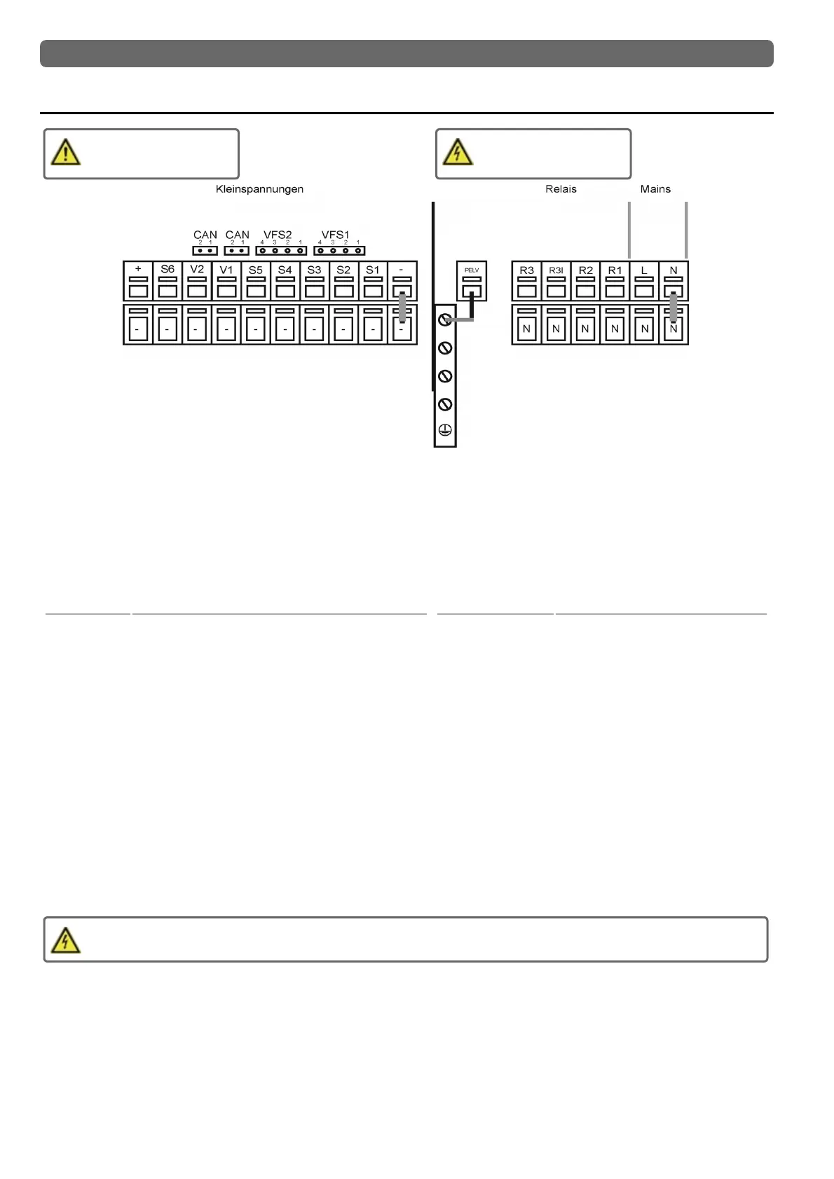
Electrical Terminals
Low voltage
max. 12 VAC / DC
Mains voltages
230 VAC 50 - 60 Hz
On the control board
LTDC Version V3 + V4:
VFS1 Grundfos Direct Sensor
VFS2 Grundfos Direct Sensor
LTDC Version V1 + V4:
CAN CAN bus connection (1=high,2=low)
CAN CAN bus connection (1=high,2=low)
Terminal: Connection for:
S1 Temperature Sensor 1
S2 Temperature Sensor 2
S3 Temperature Sensor 3
S4 Temperature Sensor 4
S5 Temperature Sensor 5
V1 speed controlled output for 0-10V / PWM high-effi-
ciency pumps
LTDC Version V3 + V4:
V2 0-10V / PWM signal output e.g. for con-
trolling high-efficiency pumps
S6 Temperature Sensor 6
+ 12V Power supply
The connection of the ground wire is made at the lower gray ter-
minal block.
Terminal: Connection for:
N Neutral conductor N
L Network outer conductor L
R1 Relays 1
R2 Relays 2
R3| Relays 3|
R3
Relays 3
The neutral conductor N must be connected to the N ter-
minal block.
The PE protective conductor must be connected to the
PE metal terminal block!
In high-efficiency pumps with 0-10V / PWM signal input,
the power supply must go through the corresponding
relay (V1 -> R1, R2 -> V2), because the relay turns on
and off together with the control signals.
At R3I are permanently 230v when the relay is inactive. Wrong wiring can damage the connected components.
10