Do you have a question about the SoundCraft 600 Series and is the answer not in the manual?
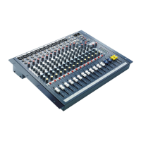
Overview of the Soundcraft Series 6000 console, its features, and applications.
Details the features and functions of the input module, including gain, EQ, and routing.
Details the features and functions of the stereo input module, including EQ and width control.
Describes the functions of the output module, including group/tape monitoring and EQ.
Explains the function of the sub switch and its effect on signal flow for subgroups.
Details how to switch operating levels between +4 dBu and -10 dBv for tape machine matching.
Explains the LED bargraph metering system and its modes (peak/VU).
Controls the overall mix output level and summing.
Selects and adjusts signals for control room and studio speakers.
Controls for the six auxiliary send sections.
Includes line-up oscillator and talkback functions.
Configures solo behavior for input modules.
Centralized muting function for channels.
Describes the input connections for monitor/effects return sections.
Details the auxiliary send outputs for the module.
Details standard input and output connector configurations.
Details connections for group, monitor, tape, and auxiliary outputs.
Details connections for control room, studio, tape, mix, and PSU.
Details optional stereo input connections via XLR and jack.
Explains the patchbay system and connection types.
Instructions for setting mains voltage and checking fuses.
Details nominal input/output levels (+4dBu, -10dBv).
Details standard XLR wiring conventions.
Essential steps for clean earthing and mains supply installation.
Procedures for connecting audio equipment and checking for noise.
Guidelines on managing signal screen connections to prevent interference.
Overview of the recording process sequences.
Steps for recording direct from mic or line input.
How to listen to recorded tracks by selecting Tape Return.
Process of building tracks while listening to previously recorded ones.
Process of combining recorded tracks with effects for the final stereo mix.
Steps and logic for troubleshooting non-functioning modules.
Procedures for safely removing modules from the console.
How to adjust VU meter drive presets for correct calibration.
Information on replacing lamps used for VU meter illumination.
Specifies the nominal internal operating level of the console.
Detailed circuit description of the input amplifier, high-pass filter, and equaliser.
Circuit details of the group and monitor sections of the output module.
Circuit details for mix summing amps, post-amp, and control room outputs.
Circuit details for auxiliary summing system and AFL LEDs.
Description of the LED bargraph metering systems.
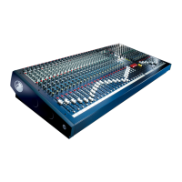
| Subgroups | 4 |
|---|---|
| Channels | 24 |
| Bus | 4 |
| Metering | LED |
| Frequency Response | 20Hz-20kHz |
| Type | Analog Mixer |
| Phantom Power | +48V (switchable on each channel) |