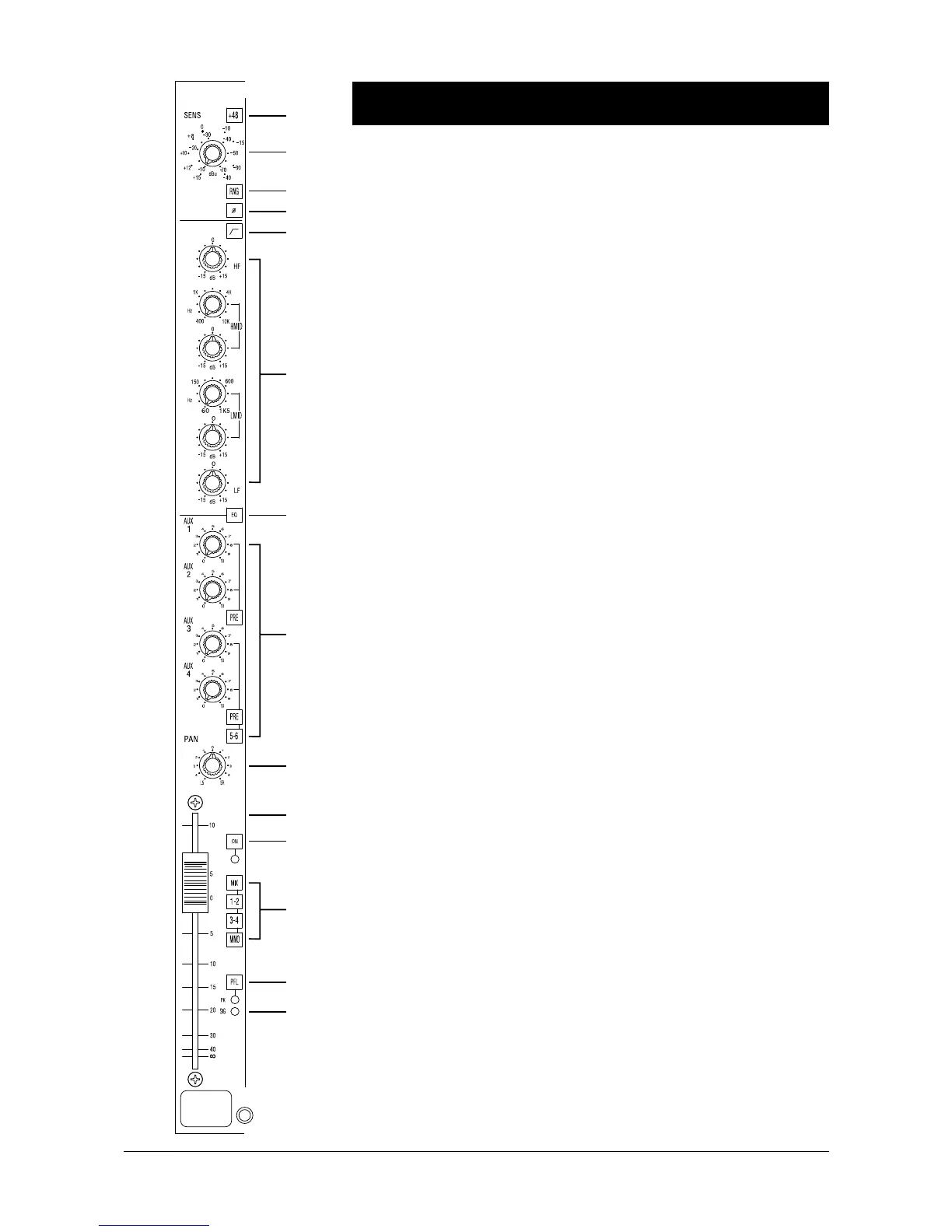
Mono Input Channel
The mono input is provided with XLR and jack connectors, either of which may be
used for any level of input signal. Normally the XLR signal is used, but inserting
a jack automatically disconnects the XLR socket, and applies the jack signal to the
input.
The channel is provided with an Insert Point using an unbalanced send and return,
at a nominal level of -2dBu. The signal is accessible via a single 1/4" jack on the
rear connector panel. The insert point is permanently pre-EQ.
1 The 48V switch applies 48V phantom power to the input XLR. Note that 48V
is never applied to the jack socket.
2 The SENS (Sensitivity) control adjusts the sensitivity of both the XLR and jack
inputs and in combination with the RNGE switch gives two sensitivity ranges:
-15dBu to -70dBu and +10dBu to -40dBu.
3 The RNGE (Range) switch lowers the sensitivity of the input when pressed,
allowing line level signals to be used.
4 The Ø (PHASE) switch reverses the phase of the selected input when pressed.
The switch should normally be released.
5 This switch inserts a second order HI-PASS FILTER into the channel path.
The frequency is fixed at 100 Hz.
Equaliser
6 The EQ section has four bands. The HF and LF sections have a shelving
response at a fixed frequency. The Two MID sections have a peaking response at
a variable frequency.
• The HF control gives 15dB of cut or boost at 12kHz.
• The LF control gives 15dB of cut or boost at 60Hz.
• The Hi-Mid control gives 15dB of cut or boost at 400-10kHz, selected by the
Hi-Mid frequency control.
• The Low-Mid control gives 15dB of cut or boost at 60Hz-1.5kHz, selected by
the Low-Mid frequency control.
7 The EQ section is switched in by the EQ switch. Toggling this switch provides
a simple method of hearing the effect of the equaliser settings.
Auxiliary Sends
8 Signal is sent to the Aux 1-6 busses via four LEVEL controls. These have unity
gain when fully clockwise, and are switched pre-or post-fader in pairs by the PRE
buttons.
The 5-6 switch switches the signal from the second pair of level controls away from
busses 3 & 4 and onto busses 5 & 6.
1
2
3
4
5
7
9
10
11
12
13
14
6
8
4.2 December 1994 Functional Descriptions
 Loading...