-5
+5
+10
-10
-15
-20
0
1
2
3
4
6
8
9
10
11
12
13
5
7
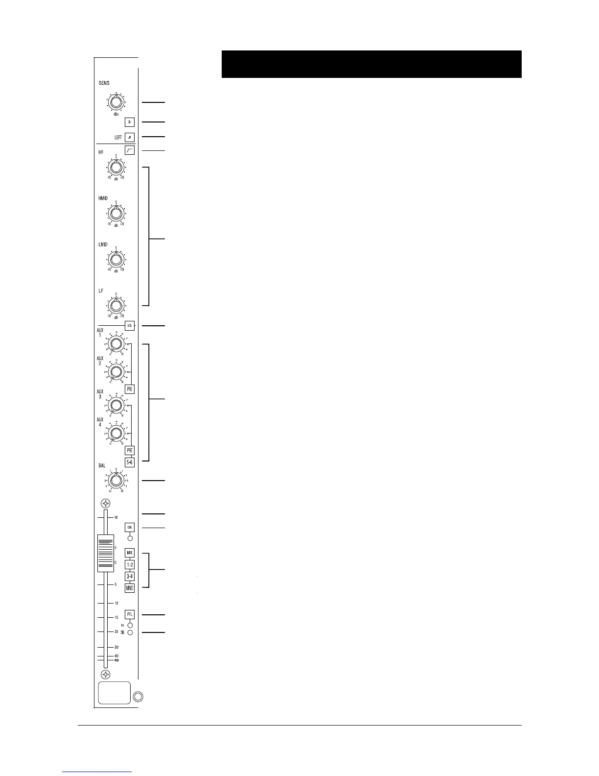
Stereo Input Channel
1 The SENS (Sensitivity) control adjusts the sensitivity of A or B inputs from
+14 to -16dBu.
2 Pressing B switches the input source from line A to line B, both of which are
electronically balanced, from 1/4" Jack inputs on the rear panel.
The left and right jacks of both A and B inputs are normalised together via the switch
contacts of the right jack so that a mono signal, plugged into the left jack only, is
fed equally to left and right.
Input B may be linked for an internal RIAA filter.
3 Pressing LEFT (Ø) PHASE inverts the phase of the left channel on the selected
input.
4 This switch inserts a second order HI-PASS FILTER into the channel path.
The frequency is fixed at 100 Hz.
Equaliser
5 The EQ section has four bands. The HF and LF sections have a shelving
response at a fixed frequency. The Two MID sections have a peak/dip response at
fixed frequencies.
• The HF control gives 15dB of cut or boost at 12kHz.
• The LF control gives 15dB of cut or boost at 60Hz.
• The Hi-Mid control gives 15dB of cut or boost at 5kHz.
• The Lo-Mid control gives 15dB of cut or boost at 250Hz.
6 The EQ section is switched in by the EQ switch. Toggling this switch provides
a simple method of hearing the effect of the equaliser settings.
Auxiliary Sends
7 Signal is sent to the Aux 1-6 busses via four LEVEL controls. These have unity
gain when fully clockwise, and are switched pre-or post-fader in pairs by the PRE
buttons.
The 5-6 switch switches the signal from the second pair of level controls away from
busses 3 & 4 and onto busses 5 & 6.
The pre or post-fader source for Aux 1 & 2 is a mono sum of the left and right
channel signals. The Pre or post-fader source for the for Aux 3 & 4 (5 & 6) can be
either stereo (left feeds 3 or 5, right feeds 4 or 6) or a mono sum. This is selected
by internal jumpers.
Functional Descriptions December 1994 4.5
 Loading...