1.800.338.7337 / www.soundoffsignal.com
ETSA48(x)CSX 0119
6. Horn Ring Standby Tone: (Alternate Horn Ring Control Must be
Disabled) Determines which tone to output when siren is in
standby and vehicle horn is pressed
ON = Air Horn Tone
OFF = Manual Button Tone
7. 8 Second Buzzer Alert: Provides audible beep whenever any
auxiliary switches are ON or level 1,2, or 3 is active.
ON = Enabled
OFF = Disabled
8. Air Horn Button Output Channels
ON = In standby mode, Horn tone is
output on Spkr A & B. When
Warning Tone is Active,
Warning Tone continues on Spkr
A & Air Horn Button Tone is
output on Spkr Diagnostic
OFF = Horn Button Tone always
produced on Spkr A & B.
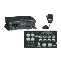
CONTROL PANEL
PSRN4CTRL2
PSRN4CTRL3
PROGRAMMING MANUAL
PROGRAMMING MODES
AUXILIARY SWITCH SETTINGS:
Refer to Siren Amplier Diagnostic Indicator Chart below for Button and LED
locations and terminology
1. Press and Hold Auxiliary Button #1 and #8 until slide switch #1 LED
ashes.
2. Press the button which setting is going to be viewed/changed 1 time.
3. Monitor the 5 LED’s for the arrow controller to determine setting
- *Arrow Controller (Left, Right, Center, OFF), Dual Output; 1 & 9
- Alternate Action Switch (Press ON / Press OFF)
- Momentary Action Switch (ON only when depressed)
- 8 Second ON Time (ON for 8 seconds when depressed)
- Level 1 Disable (Turns OFF Level 1 Output)
- Level 2 Disable (Turns OFF Level 2 Output)
- Left Arrow, Single Output
- Right Arrow, Single Output
- Center Arrow, Single Output
- Warning Bar Output
4. Press and release button until desired mode is selected.
5. Continue steps 2-3 for any other buttons that need to be programmed.
*Can only be programmed to one button
and will disable Left, Right and Center
Arrow Single Outputs if they are used.
Denotes Factory Default Setting
Default Settings:
Button #1: Arrow Controller
Button #2-7: Alternate Action Switch
Button #8: 8 Second ON Time
Slide switch mapping programming:
Allows the operator to have the siren automatically turn on auxiliary
push-buttons or tones based on the position of the slide switch.
If an auxiliary or tone push-button is programmed to turn ON when
the slide switch position is selected, the auxiliary push-button
will turn OFF when the programmed slide switch position is no
longer selected.
The operator can override the automatic activation of the auxiliary
push-button by momentarily pressing the auxiliary push-button.
To program:
1. Press auxiliary push-buttons ‘4’ and ‘5’ for until Radio
Rebroadcast indicator LED ashes.
2. Move slide switch to desired position.
3. Press auxiliary push-buttons ‘1’ – ‘8’ and or Siren Control Select
as required.
4. Repeat steps 2 and 3 for other slide switch positions as
required.
5. Place appropriate button legend over activity indicator for each
programmed button.
LED ON
(GREEN)
Auxiliary push-button or Siren Control Select
will automatically turn ON when level switch
position is activated.
LED OFF
(RED OR OFF)
Auxiliary push-button or Siren Control Select
will NOT automatically turn ON when level
switch position is activated.
DIAG S1 S2 CONDITION
FLASHING OFF ON UNDER-VOLTAGE
FLASHING ON OFF OVER-VOLTAGE
FLASHING FLASHING - COMM FAULT - RELAY
FLASHING - FLASHING COMM FAULT - AMP
FLASHING FLASHING FLASHING COMM FAULT -RELAY AND AMP
- - - -
*OFF ON - SPKR 1 IS ACTIVE
*OFF - ON SPKR 2 IS ACTIVE
*OFF OFF - SPKR 1 IS NOT-FUNCTIONING
*OFF - OFF SPKR 2 IS NOT-FUNCTIONING
SIREN AMPLIFIER DIAGNOSTIC
INDICATORS:
* SIREN AUDIO BUTTON ACTIVATED
(EXCEPT RADIO REBROADCAST)
8
OTHER MODES CONTINUED:
5. Power Down: Determines siren operation after ignition wire
input has no voltage
ON = Timed Power Down: Siren will
power down 10 min. after last
activity.
OFF = Immediate Power Down: Siren
will go into lowest power state
within 10 seconds.
 Loading...