– 32 –
Inverter Air-to-Water Heat Pump
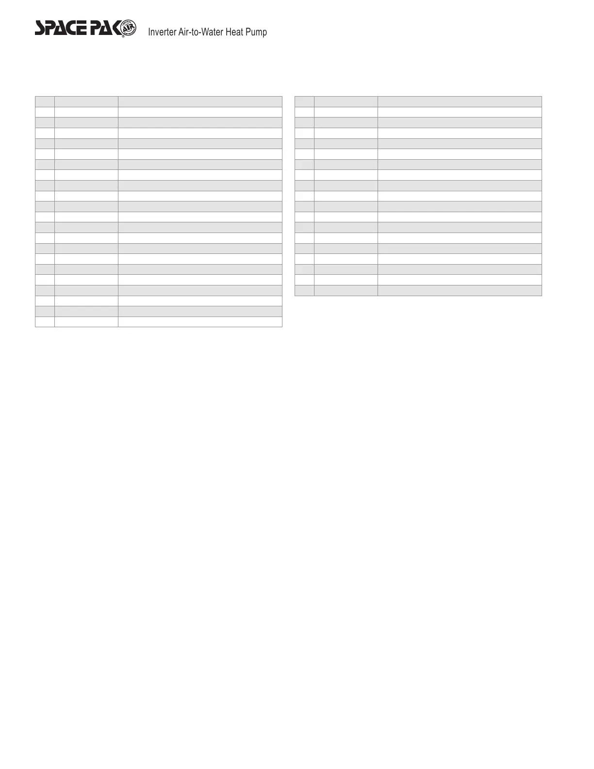
No. Main Board Instruction
1 N Power Null Wire
2 L Power Live Wire
3 RO 01 Not Used
4 RO 02 Pump
5 RO 03 4-Way Valve
6 RO 04 Fan
7 RO 05 Not Used
8 RO 06 Def Heating
9 RO 07 Crankshaft Heating
10 RO 08 Spray Valve
11 RO 09 Auxiliary Electric Heating
12 RO 10-RO 18 Not Used
13 AI 01 Inlet Temperature Sensor
14 AI 02 Outlet Temperature Sensor
15 AI 03 Discharge Temperature Sensor
16 AI 04 Not Used
17 AI 05 Suction Temperature Sensor
18 AI 06 Coil Temperature Sensor
19 AI 07 Environment Temperature Sensor
20 AI 08-AI 20 Not Used
21 AI 21 Suction Pressure Input
22 AI 22 Discharge Pressure Input
No. Main Board Instruction
23 DI 01 High Voltage Switch Input
24 DI 02 Low Voltage Switch Input
25 DI 03 Flow Switch Input
26 DI 04 Emergency Switch Input
27 DI 05 Mode Switch
28 DI 06 Master and Slave Switch
29 DI 07 Electric Heating Overload Protection Switch
30 DI 08-DI 10 Not Used
31 A 01-A 02 Not Used
32 D01-D02_PWM Not Used
33 D10-D12_PWM Not Used
34 12V Wired Controller 12V
35 485-B Wired Controller 485-B
36 485-A Wired Controller 485-A
37 GND Wired Controller GND
38 CAN-L Not Used
39 CAN-H Not Used
40 CN-1 Electronic Expansion Valve A
41 CN2-CN4 Not Used
Wiring Diagrams and Definitions