– 7 –
Inverter Air-to-Water Heat Pump
Glycol/Water System
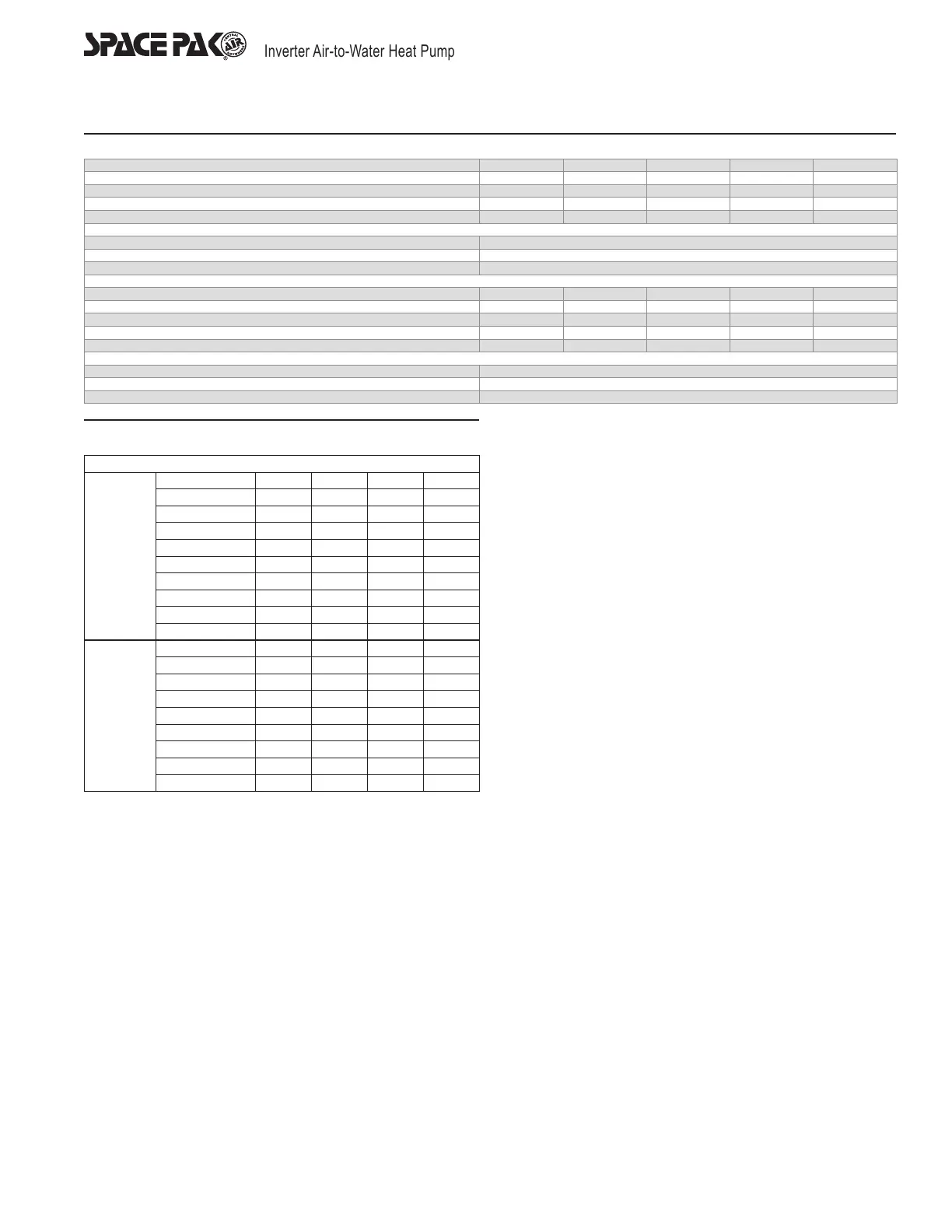
Figure 1 SIM Glycol Concentrations (10% Minimum, 50% Maximum)
Ethylene Glycol % 10 20 30 40 50
Min. Ambient Temp for Operation 23°F/-5°C 14°F/-10°C 2°F/-17°C -13°F/-25°C -36°F/-38°C
SpacePak Capacity Multiplier 0.98 0.96 0.93 0.91 0.89
Pressure Drop Multiplier (Cooling) 1.06 1.12 1.16 1.25 1.36
Pressure Drop Multiplier (Heating) 1.06 1.12 1.16 1.22 1.28
Minimum Expansion Volume / System Volume
Heating and Cooling (Gallons) 1 gallon expansion per 15 gallons system volume
Heating only, HP only (Gallons) 1 gallon expansion per 20 gallons system volume
Heating Only, with Boiler (Gallons) 1 gallon expansion per 15 gallons system volume
Propylene Glycol % 10 20 30 40 50
Min. Ambient Temp for Operation 26°F/-3°C 18°F/-8°C 8°F/-13°C -7°F/-22°C -29°F/-34°C
SpacePak Capacity Multiplier 0.99 0.98 0.96 0.93 0.88
Pressure Drop Multiplier (Cooling) 1.10 1.20 1.34 1.5 1.65
Pressure Drop Multiplier (Heating) 1.10 1.20 1.34 1.46 1.5
Minimum Expansion Volume / System Volume
Heating and Cooling 1 gallon expansion per 15 gallons system volume
Heating only, HP only 1 gallon expansion per 20 gallons system volume
Heating only, with Boiler 1 gallon expansion per 15 gallons system volume
Glycol/Water System Design
Each SIM Heat Pump has a recommended ow that should be
maintained during all times of operation. For the SIM-060, the
recommended ow is 13GPM at which the head loss is 25ft W.C,
11PSI or 73kPa. For the SIM-036 the recommended water ow is
7GPM at which the head loss is 6 ft W.C. or 6 P.S.I. These head loss
values are based upon pure water, see Figure 1 for multipliers to
correct for various concentrations of anti-freeze solution.
Note: these are the recommended ow values. Should the ow drop
signicantly below this value, the heat pump will shut down and
display the code FL on the display. This is not an indication of a fault
in the heat pump, but rather points to insufcient pump or plumbing
capacity, or air trapped within the system.
System Volume and Expansion Volume
To ensure smooth temperature control and minimize cycling of
refrigeration system, all installations must have total circulating
volumes equal to or greater than 7-1/2 gallons per nominal ton
of the unit performance (The greater of either heating or cooling
produced). In other words, in the case of a four ton heat pump the
minimum total system volume is 4x7-1/2=30 gallons. Multiple heat
pump installations that are operating in a staged conguration follow
the same rule, so that only a single heat pump tonnage needs to be
considered. Additionally, the system requires an expansion volume
(air) to compensate for the change in volume of the glycol mixture
as it heats and cools, see Figure 1 for expansion volume.
A typical multiple heat pump installation may actually have a volume
far greater than the minimum required, and it is this entire volume
that must be considered when sizing the expansion tank.
Note that the nominal expansion tank volume is not the same as the
expansion volume. If the actual air volume is not published, consider
it to be no more than half the nominal volume.
As an example, a four ton nominal heat pump, used for both heating
and cooling, requires a minimum of thirty gallons of circulated
system volume. A 40 gallon buffer tank is selected for best operation.
When the system installation is complete, the total liquid volume
of plumbing, air handlers, and heat pump is 45 gallons. (Note the
expansion tank, no matter how large, is not considered circulated
volume) This requires an acceptance volume of 3 gallons. If the
acceptance volume is not specied, assume it is 50% of the total
volume. Therefore, this system would require an expansion tank of 3
gallons acceptance volume, or six gallons nominal full volume.
Air Separator
Locate at least one high efciency air separator as shown in the
piping to remove any air from the system.
Figure 2
Piping Pressure Losses*
Pressure Drop, Ft H2O/100ft*
Pex
Pipe
Flow Rate GPM 1" 1-1/4" 1-1/2" 2"
6 5.5 1.7 - -
7 7.2 2.5 1.5 -
8 9.1 3.4 1.8 -
9 11.1 4.3 2.1 0.5
10 13.4 5.2 2.4 0.6
11 15.9 6.2 2.8 0.7
12 18.5 7.2 3.2 0.9
14 - 9.4 4.2 1.2
16 - 11.8 5.4 1.6
Copper
Pipe
(Type L)
6 1.0 - - -
7 1.4 0.5 - -
8 1.8 0.7 - -
9 2.2 0.8 0.3 -
10 2.7 1.0 0.4 -
11 3.2 1.2 0.5 0.1
12 3.8 1.4 0.6 0.1
14 - 1.8 0.8 0.2
16 - - 1.0 0.3
*Remember to check the CV rating of your ttings and valves to
make sure you're getting the required ow through the equipment.
 Loading...