Seaich Corporation, LLC. All rights reserved. www.seaich.com
|
Spacerails, LLC. www.spacerails.com Page 5
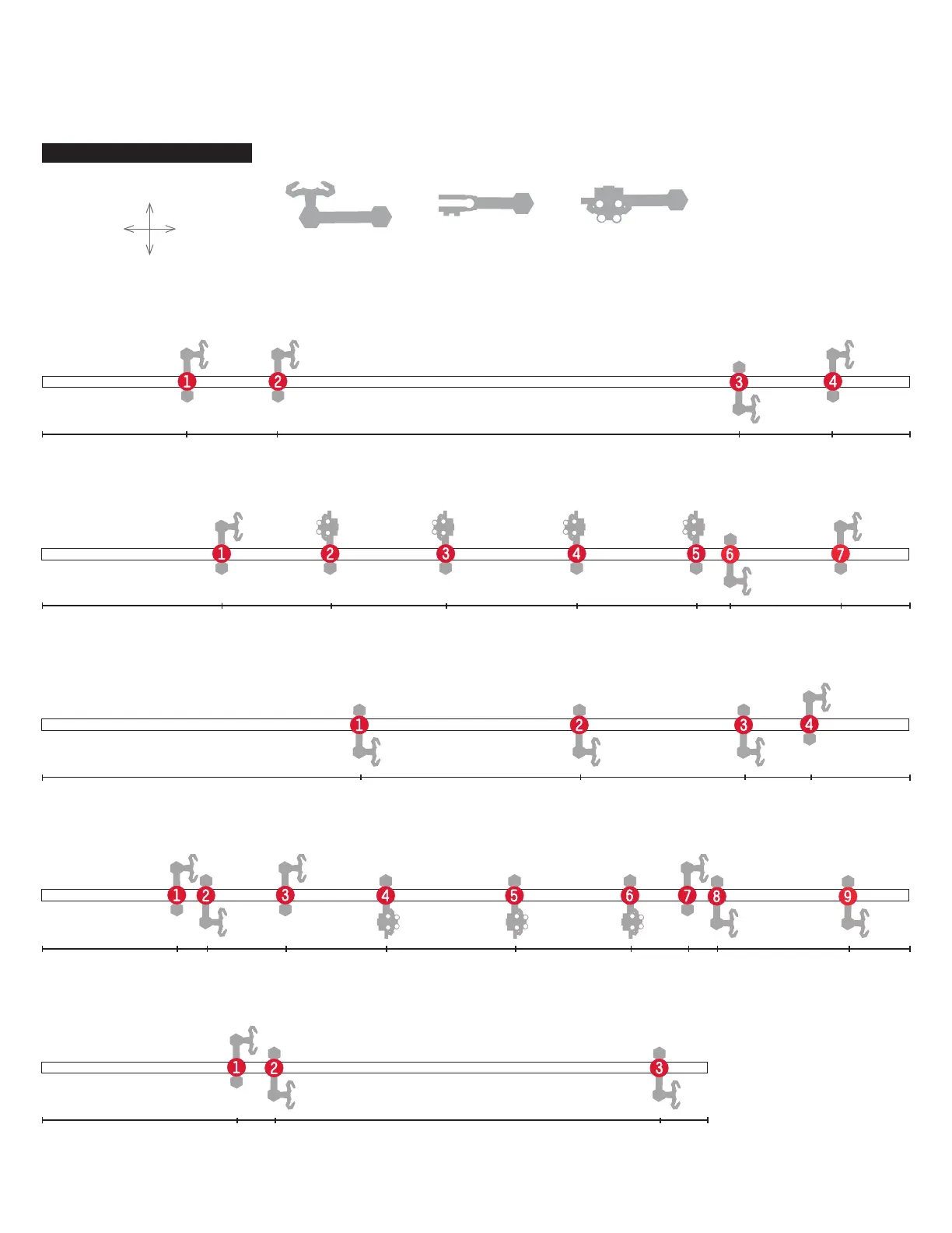
This is how the arm types are referenced on the shaft drawings.
Arm A Arm B
See-Saw Arm
Step 2: Attach each arm as shown in step 1 with the orientation and location shown here. In later steps the letter of each
shaft and number of each arm will guide in the installation of the rails. For example arm A-3 below is 314 mm from the
base and faces the front. Illustration is approximately 50% of actual size. All shaft measurements are in Millimeters.
Shaft A
Shaft B
Shaft C
Shaft D
Shaft E
65
81 130
143
63
88 105 278
73 110 156 213 265 291 303 363
242 316 346
182 241 295 310 360
106 356314 391
391
391
391
300
TOP
BASE
BACK
OF BASE
FRONT
OF BASE
SHAFT TO BASE ORIENTATION