This document provides instructions for assembling the SpaceRails Level 4 marble roller coaster. It outlines the components included, required tools, and step-by-step assembly procedures, along with tips for optimal performance and safety warnings.
Function Description
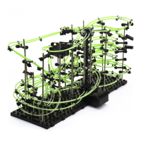
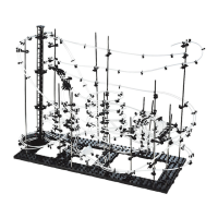
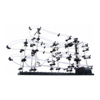
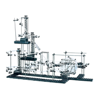
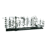
The SpaceRails Level 4 is a complex marble roller coaster designed for users aged 8 and older. Its primary function is to provide an engaging and challenging construction experience, culminating in a functional marble run that demonstrates principles of gravity and motion. Marbles are lifted by an elevator mechanism to the highest point of the track, from where they descend through a series of intricate loops, curves, splits, and see-saw sections before returning to the elevator to repeat the cycle. The design allows for continuous marble movement, creating a dynamic and visually appealing display.
Usage Features
Assembly and Construction
The assembly process is divided into several key stages: arm assembly, rail splitter assembly, see-saw assembly, base assembly, elevator assembly, starter assembly, shaft assembly, and rail installation. Each stage is detailed with illustrations and step-by-step instructions.
Arm Assembly:
- Step 1: Attach one Arm Holder A and one Arm Holder B with an Arm Sheath. It's important to note that the hole shapes of the Arm Holder and Arm Sheath differ, guiding correct alignment.
- Step 2: Insert an Arm Clip into Arm Holder A, sliding the circular part between the matching parts on the Arm Holder.
- Step 3: Insert an Arm Lock through Arm Holder A and the Arm Clip, ensuring the tab faces upward.
- Step 4: Turn the Arm Lock counter-clockwise to secure the Arm Clip in place.
- Caution: To prevent damage, avoid moving or adjusting the Rail Clip while it's locked in the arm. To reposition, release the Arm Lock by turning it clockwise, adjust the Rail Clip, then re-secure the Arm Lock. A total of 66 arm assemblies are required for connecting shafts to rails.
Rail Splitters:
- Step 1: Attach one Rail Clip to each post of the Rail Splitter.
See-Saw Assembly:
- Step 1: Cut two rail pieces to 55mm and insert one into each hole on the See-Saw.
- Step 2: Insert the See-Saw Arm and the rails into the Rail Clip. Adjustments to the See-Saw may be necessary after installation if it shifts.
- Step 3: Insert the See-Saw into Arm Holder B.
- Step 4: Insert the See-Saw into the Rail Stand (300mm Shaft). Refer to the shaft assembly section for precise placement. Three See-Saw Arms are included.
Base Assembly:
- Step 1: Interlock the Base block tabs as illustrated. Nine base blocks are provided.
- Step 2: Press Base Holder A and Base Holder B pieces into the Base blocks for a secure hold. Four Base Holder A and six Base Holder B pieces are included. Note that Base Holder B is used in some instances where Base Holder A might be expected.
Elevator Assembly:
- Step 1: Place a shaft into the white hole on the Power Box.
- Step 2: Connect Elevator Helix pieces together, with the male part facing up, to fill the shaft. The first Elevator Helix piece should be installed male side up and rotated until it slides into place and engages with the driver at the base of the Power Box. Twelve Elevator Helix pieces are included.
- Step 3: Once the corkscrew (elevator helix) is built, attach three 300mm support shafts to the Power Box.
- Step 4: Connect one Rail Clip to each Elevator Ring. Install the Elevator Ring with tabs facing up. Three Elevator Rings are included.
- Step 5: Place the three Elevator Rings over the three shafts.
- Step 6: Place the Elevator Cover onto the top of the elevator assembly. One Elevator Cover is included.
- Step 7: Attach an Elevator Guard to each Elevator Ring, then to the right side of the Rail Clip. Four Elevator Guards are included.
- Note: Marbles may fall out of the elevator if they enter too fast.
Starter Assembly:
- Step 1: Connect Arm Holder B to a 300mm Shaft and insert an Arm Lock.
- Step 2: Connect the Starter pegs to the Arm Holder.
- Step 3: Ensure the Starter is at a slight angle for smooth marble flow.
- Step 4: Attach Rail Clips and the Start Block Cover to the Starter. One Start Block and one Start Block Cover are included.
Shaft Assembly:
- Step 1: Slide Arm Holder B of each arm onto a shaft and lock it in place with an Arm Lock. Refer to the full-size drawings for the orientation and location of each arm.
- Step 2: Attach each Arm and See-Saw Arm as shown, noting the orientation and location. Shaft measurements are in millimeters. The illustration is approximately 51% of actual size.
- Step 3: Place shafts and the elevator into the base. Push shafts into the base holes until sturdy. Attach the Power Box Stand to the Power Box, firmly seating its posts into the base holes. One Power Box Stand is included.
- Step 4: Attach the 90mm Shaft Connector to Shafts K and N. Attach the 50mm Shaft Connector to Shafts F and G. One 90mm Shaft Connector and one 50mm Shaft Connector are included. Sixteen 300mm shafts and five 200mm shafts are included.
Rail Cutting:
- Step 1: Measure each rail section and mark the cutting point with a pen.
- Step 2: Cut each section at a 90-degree angle.
- Tip: To avoid re-cutting and wasting rail, cut generously (slightly longer than needed) initially, as excess can always be trimmed. Rail lengths are illustrated at approximately 5% scale; use a ruler for accurate measurements, especially for longer segments. Refer to the included insert for 1:1 scale rail measurements. A total of 26,000mm of rail is provided.
Rail Installation (Rail A, B, C, D, E, F, G):
-
Rail A (300 cm):
- Step 1: Start at the top right Elevator Ring (1R-1). Connect Rail A to a Rail Clip. Curve the rail to connect to Arm P-1, then Arm I-1 (keeping rail tight), then Arm D-1. Curve and connect to C-1. Attach Rail Clips every 8-10 cm for stability and parallel alignment.
- Step 2 (Loop): Angle arms and Arm Clips to create a loop. Start at Arm F-1, loop to C-2, then E-2 for a circular shape. Continue with B-1, E-1, D-5, then D-2 to complete three loops.
- Step 3: Keep rail tight, connect to I-4, then L-5. Curve and attach to P-5, Q-8, N-3, and finish at Elevator Exit (R-3).
- Fine Tune: After completing each rail section, run a marble to check travel. Adjust as needed, especially the loop and rail angles.
-
Rails B, C, and D:
- Step 1 (Rail B, 5 cm): Start at the top center Elevator Ring (2R-1). Connect Rail B to a Rail Clip. Connect the other end to the Rail Splitter (which is not supported by a shaft).
- Step 2 (Rail C, 45 cm): Connect Rail C to the right side of the Rail Splitter. Curve and connect to L-6, then O-6, then P-4. The rail will end above the two See-Saws. Use a marble to adjust the See-Saws so the marble falls onto each See-Saw Arm, tipping it forward onto the one beneath.
- Step 3 (Rail D, 200 cm): Connect Rail D to the left part of the Rail Splitter. Continue to D-6 and curve around to C-3. Continue in a downward slope to J-1, then loop and attach to K-2, then K-1.
- Step 4: Continue Rail D in a curve and attach to L-4, then I-3. Curve the rail the opposite way and connect to G-2 (under the Start Block), and finish at Elevator Exit R-3.
-
Rail E (200 cm):
- Step 1: Start at the middle center Elevator Ring (3R-2). Connect Rail E to a Rail Clip. Continue between Shaft I and J. Curve to connect to Arm L-2, then N-1. Line the rail around the outside of the structure to A-1, then D-4, L-3, and P-2. The rail ends above the See-Saw Arm.
-
Rails F and G:
- Note: It may be helpful to start with the majority of the rail towards the back of the base. A small portion of the rail end can then be threaded through the triple loop and connected back to the elevator. When constructing the spiral, guide excess rail to easily attach to Rail Clips.
- Step 1 (Rail F, 45 cm): Start at the top left Elevator Entry 3(R-3). Connect Rail F to a Rail Clip. Curve and connect to Arm G-1, then Arm A-2. Continue the curve and connect to the Start Part.
- Step 2 (Rail G, 350 cm): Start at the bottom left Elevator Entry 3(R-3). Connect Rail G to a Rail Clip. Curve and connect to G-3, then through the triple loop to D-3. Keep rail tight, connect to I-2, then L-1 and O-1. Curve and attach to Q-1.
- Step 3 (Spiral): Connect rail to Arm M-1, then curve tightly to O-2, then Q-2. Continue the spiral upward to M-2, O-3, Q-3, M-3, O-4, and Q-4. Finish the top of the spiral with M-4, O-5, and Q-6. Bring the rail out and connect to Arm N-2, then back to the Start Block.
- Fine Tune: After completing each rail section, run a marble to check travel. Adjust as needed, especially the spiral and rail angles.
General Construction Tips
- Connecting Rails to Arms: Press rails into the arm until a click is heard, indicating it's locked.
- Rail Joining for Custom Designs: Use Rail Couplings to extend rail sections for custom layouts. Ten Rail Couplings are included.
- Angling the Arms: Install arms at an angle that matches the incline of the rails.
- Railroad Stability: Attach Rail Clips as needed to maintain stability on longer track segments. Seventy Rail Clips are included.
- Elevator Exit: When installing elevator exit rails, pull them close to the Elevator Helix to ensure smooth marble entry into the roller coaster.
- Smooth Rails: Ensure rails connect smoothly, free of bumps, twists, or kinks for efficient marble travel.
- Wire Cutters or Utility Scissors: For cutting rails to specified lengths.
- Pen or Marker: For marking rail cutting points.
- 3 AA Batteries (newer models) or 1 C Battery: To power the elevator mechanism.
- Ruler (in centimeters): For accurate rail measurement.
Maintenance Features
The manual emphasizes careful assembly to ensure the longevity and proper functioning of the SpaceRails Level 4. While specific maintenance steps are not detailed, the following can be inferred from the usage features and warnings:
- Careful Handling of Parts: The "To avoid damaging parts" warning regarding the Rail Clip suggests that delicate handling during assembly and adjustment is crucial for preventing wear and tear.
- Proper Rail Alignment: The "Smooth rails for efficient travel" tip implies that maintaining smooth, bump-free rail connections is essential for continuous operation and prevents marbles from getting stuck or derailing, which could lead to damage over time.
- Regular Adjustments: The "Fine Tune" sections for rail installation indicate that periodic adjustments to arm angles and rail positions may be necessary to ensure optimal marble flow, especially if performance degrades over time.
- Battery Replacement: The requirement for batteries implies that the elevator mechanism will cease to function once batteries are depleted, necessitating replacement to maintain continuous operation.
- Cleaning: Although not explicitly stated, keeping the tracks free of dust and debris would likely contribute to smoother marble travel and prevent blockages.
- Marble Usage: The warning "only insert the included marbles into the elevator" is a critical maintenance instruction. Using marbles of incorrect size or material could potentially damage the elevator mechanism or cause blockages in the track, leading to operational issues. Four marbles are included.
By following the detailed assembly instructions and adhering to the usage tips, users can ensure the SpaceRails Level 4 operates as intended and remains a source of entertainment.