Seaich Corporation, LLC. All rights reserved. www.seaich.com
|
Spacerails, LLC. www.spacerails.com Page 5
600
550
508
442
380
62
Shaft A
600
578
80
116
Shaft B
157
227
300
Shaft C
391
365
210
128
Shaft D
TOP
BASE
BACK
OF BASE
FRONT
OF BASE
SHAFT TO BASE ORIENTATION
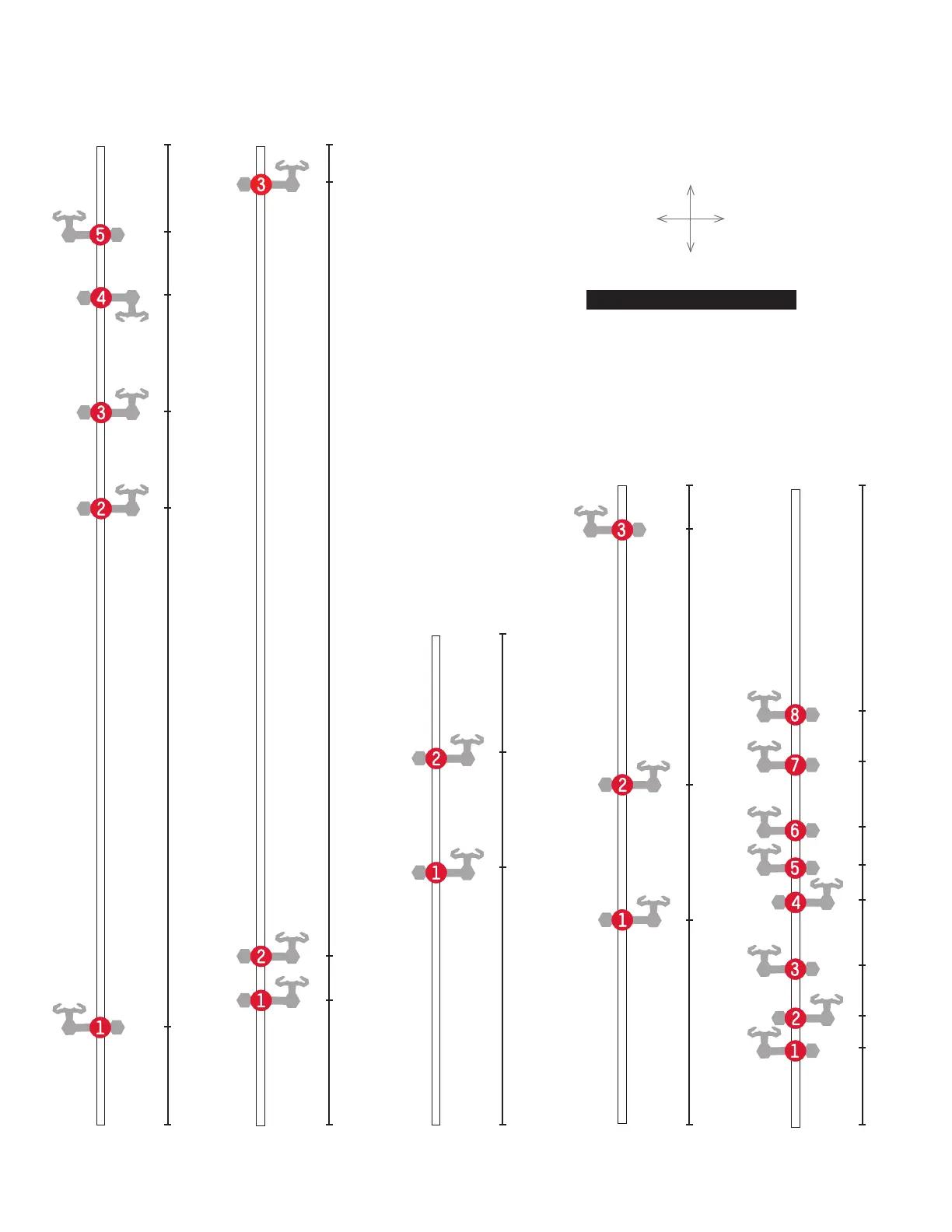
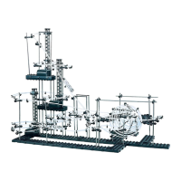
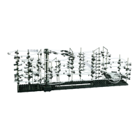
Step 2: Attach each arm as shown in step 1 with the orientation and location shown here. In later steps the letter of each
shaft and number of each arm will guide in the installation of the rails. For example arm A-3 below is 442 mm from the
base. Illustration is approximately 37% of actual size. All shaft measurements are in Millimeters.
391
49
65
98
140
160
183
223
254
Shaft E