Page 4 Seaich Corporation, LLC. All rights reserved. www.seaich.com
|
Spacerails, LLC. www.spacerails.com
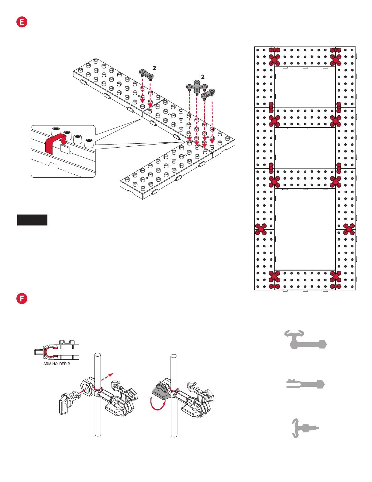
Step 1: Interlock all
base block tabs as
shown above.
Step 2: Press Base Holder A and
Base Holder B pieces into the base
blocks for a more secure hold.
This is how the arm types are
referenced on the shaft drawings.
Illustration of base with tabs
locked and Base Holders installed.
Approximately 18% of actual size.
Step 1: Slide Arm Holder B of each arm on to a shaft and lock in
place with Arm Lock. Refer to the next page for orientation and
location of each arm.
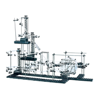
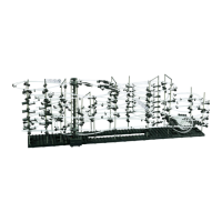
SHAFT ASSEMBLY
NOTE:
Please see the included full size drawings for the next several steps.
This will simplify the positioning of base, arms, shafts, and the rail
cut lengths.
BASE ASSEMBLY
Arm A
Arm B
Arm C