Optional Features
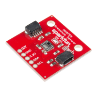
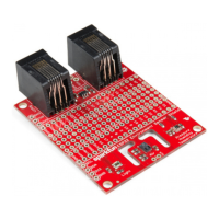
There are several jumpers on board that can be changed to facilitate several different functions. The first of which is the I C pull-up jumper, highlighted
below. If you have your own I C pull ups, you can remove the solder from this jumper.
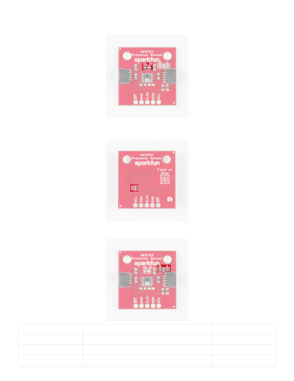
The JP8 jumper on the back of the board (highlighted below) can be sliced with a hobby knife to disable the interrupt capability. The “Field of View” text
and box shows the field of view of each of the 4 sensors. From the sensor’s point of view, channel 1 is on top, 2 is on left, 3 is on bottom, and 4 is on
the right.
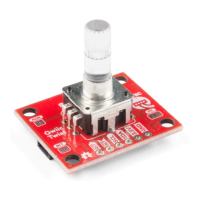
Addresses 0 and 1 can be used to change the I C address of the board in case you have multiple devices using the same address. The below table
shows the addresses that correspond to the different combinations of opened and closed jumpers.
Address 0 Address 1 I C Address
0 0 0x64
0 1 0x65
1 0 0x67
2
2
2
2