16 17
1
2
3
4
R L
SPEAKER LEVEL INPUTS
ID CODE
SA 2.1 Transmitter
PRE-AMP INPUTS
DC18V/400mA
16AWG Stranded
(minimum)
Speaker Wire
White Stripe
To Positive
White Stripe
To Positive
Receiver/Amplifier
Speaker Out Terminals
18VDC 400mA
Power Supply
To unswitched outlet
DC 24V/4.75A
ANT
SUB OUT
1
2
3
4
ID CODE
SA 2.1 Receiver
SPEAKER LEVEL OUTPUTS
16AWG Stranded
(minimum)
Speaker Wire
White Stripe
To Positive
White Stripe
To Positive
Speaker Terminals
24VDC 4.75A
Power Supply
To unswitched outlet
CONNECTIONS
CONNECTIONS
SA 2.1 Transmitter/Receiver Connections
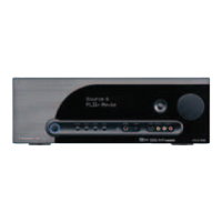
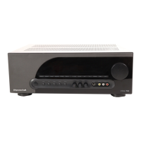
Figure 11 SA 2.1 Transmitter Speaker Level Input Connections
Figure 12 SA 2.1 Receiver Speaker Level Output Connections
1
2
3
4
R L
SPEAKER LEVEL INPUTS
ID CODE
SA 2.1 Transmitter
PRE-AMP INPUTS
DC18V/400mA
R L
PRE-AMP OUT
Stereo RCA-RCA
Patch Cable
18VDC 400mA
Power Supply
To unswitched outlet
DC 24V/4.75A
ANT
SUB OUT
1
2
3
4
ID CODE
SA 2.1 Receiver
SPEAKER LEVEL OUTPUTS
16AWG Stranded
(minimum)
Speaker Wire
White Stripe
To Positive
White Stripe
To Positive
Speaker Terminals
24VDC 4.75A
Power Supply
To unswitched outlet
LINE INL R
Stereo
Mini-RCA
Patch Cable
Subwoofer
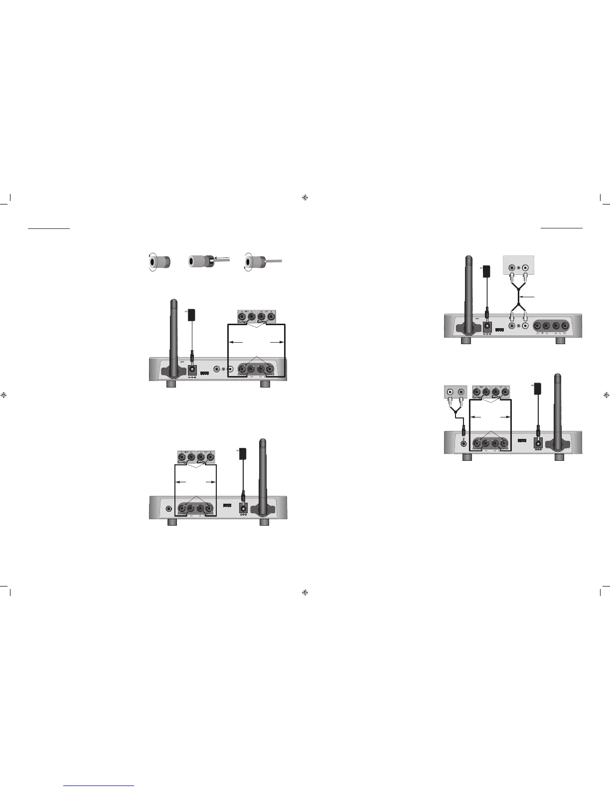
Figure 13 SA 2.1 Transmitter Pre-amp Input Connections
Figure 14 SA 2.1 Receiver Speakers with Sub Out Connections
Speaker Level Connections (SA 2.1 Transmitter)
NOTE: Be sure all system components are turned
OFF and disconnected from AC power before
making any connections to avoid potential
damage to the equipment and electrical
shock.
1. Use 16AWG (min) 2-conductor stranded
speaker wire for all speaker connections.
2. Strip approximately 1/2 to 3/4 of an inch
off the ends and twist the strands together
so there are no loose ends that can cause
shorts.
3. If connecting the SA 2.1 Transmitter to the
speaker level output on the audio receiver/
amplier, connect to the audio receiver/am-
plier speaker out terminals as appropriate.
Please refer to the receiver/amplier owners
manual for additional information.
4. Loosen the SA 2.1 Transmitter Speaker Level
Input Terminals as shown in Figure 10 so
there is enough room between the post and
the collar to feed the stripped wire through
without damaging the strands.
5. Tighten the post to secure the wire.
6. Repeat for left and right speakers, + and -.
7. Conrm connections and polarity on both
the audio receiver and SA 2.1 Transmitter.
Speaker Level Connections (SA 2.1 Receiver)
1. Loosen the SA 2.1 Receiver Speaker Level
Output Terminals as shown in Figure 10 so
there is enough room between the post and
the collar to feed the stripped wire through
without damaging the strands.
2. Tighten the post to secure the wire.
3. Repeat for left and right speakers, + and -.
4. Conrm connections and polarity.
5. Connect the speaker wires to the appropri-
ate + and - terminals on the left and right
speakers.
6. Conrm connections and polarity.
Figure 10 Bare Wire Connections
Line Level Connections (SA 2.1 Transmitter)
NOTE: Be sure all system components are turned
OFF and disconnected from AC power before
making any connections to avoid potential
damage to the equipment and electrical
shock.
1. Using a stereo RCA-RCA patch cable with
gold ends, connect the left and right xed
line level audio outputs of a CD player, MP3
player, etc; or variable pre-amp level output
of an audio receiver to the left and right
Pre-Amp Inputs on the SA 2.1 Transmitter as
shown in Figure 13.
Subwoofer Connections (SA 2.1 Receiver)
1. The SUB-OUT is a full-band (20-20kHz) left and
right channel line level output. This output
can be used as a wireless ‘LFE’ channel or
as wireless ‘full range’ channels.
LFE - Using a mono mini to RCA cable, con-
nect to the LFE IN jack on a powered sub-
woofer. Only the frequencies output by the
A/V Receiver LFE OUT (and broadcast from
the SonicAir Transmitter) will be output. The
subwoofer crossover controls will have no
affect on the subwoofer LFE IN.
NOTE: A/V Receiver LFE OUT should be con-
nected to the Sonic Air Transmitter Left Pre-
amp Input.
Subwoofer - Using a stereo 3.5mm mini to
RCA cable, connect to the L & R LINE INs
on a powered subwoofer with variable
crossover and level controls. Do not con-
nect to the LFE Input on the subwoofer. The
subwoofer LFE input is not adjustable with its
crossover control. Without setting a cross-
over point on the sub, the sub will output
higher frequency content with less than de-
sirable results. Please refer to the subwoofer
owners manual for instructions on setting the
subwoofer crossover point and volume.
NOTE 2: If using the Sub Out connection, use
of a subwoofer with audio sensing is recom-
mended. This will allow the sub to turn ON
automatically when audio signal is present
on the SA 2.1 Receiver Sub Out and turn
OFF after there has been no signal for the
duration specied by the manufacturer. All
SpeakerCraft powered subwoofers feature
audio sensing.
SPEAKER LEVEL INPUT MAX INPUT VOLTAGE:
14.5V AC RMS
SPEAKER LEVEL OUTPUT POWER: 50 WATTS PER
CHANNEL; MAX LOAD: 4 OHMS
SPEAKER LEVEL OUTPUT POWER: 50 WATTS PER
CHANNEL; MAX LOAD: 4 OHMS

 Loading...