EasyManua.ls Logo

Speakman S-1496-AF - User Manual

Speakman S-1496-AF
4 pages
Print Icon
To Next Page IconTo Next Page
Loading...
INSTRUCTIONS FOR MODELS
92-S-1496-98-03
For additional assistance or service please contact:
SPEAKMAN
®
800-537-2107
customerservice@speakman.com
www.speakman.com
S-1496-AF
S-1498-LH
* Shower head may
vary between models.
HELPFUL TOOLS & SUPPLIES:
TOOLS AND SUPPLIES
Pencil
Adjustable
Wrench
Flat Tip
Screwdriver
Phillips
Screwdriver
Thread Seal
Tape
3/32" Hex Key Wrench
(Included)
Measuring
Tape
Safety
Glasses
Level
Warranty information can be found at:
www.speakman.com
WARRANTY
Your new Shower/Bath Valve is designed for years
of trouble-free performance. Keep it looking new by
cleaning it periodically with a soft cloth. The use of
harsh chemicals and abrasives on any of the
Speakman custom finish products may damage the
finish and void the product warranty. Please be sure
to only use approved cleaners. Please contact
Speakman for any clarification of acceptable
cleaners.
This type of valve must be cleaned and maintained
on a regular basis. Periodic maintenance should be
performed at least every 12 months or after any
changes have been made to the building’s plumbing
system. Valves that are installed outdoors should be
winterized by removing all of the internal parts and
removing any standing water from the valve.
Quarterly the maximum hot temperature setting (TLS)
should be checked and adjusted accordingly.
MAINTENANCE
Cover your drain to prevent loss of parts. Be sure to
wear eye protection while cutting pipe.
SAFETY TIPS
IMPORTANT
• Be sure to read instructions thoroughly before
beginning installation.
• Be sure to have properly adjusted the Temperature
Limiting Stop (TLS) as outlined in this Installation
Manual.
• Inspect all connections after installation of valve.
• This valve has an operating range of 20-80 Psi.
• This valve is designed to be used in conjunction
with a shower head rated at 1.75 gpm (6.6 L/min)
or higher flow rate.
NOTE: This installation manual covers several
models of valves. While the appearance of your
valve may differ from those shown, the installation
method is the same.
Maximum water pressure: 125 psi static; minimum
water pressure: 20 psi flowing; minimum cold
supply temperature: 40 °F; maximum hot supply
temperature: 160 °F.
FREEZE PROTECTION
Freeze damage to the shower unit will void the Freeze damage to the shower unit will void the
warranty. It is important to winterize the complete warranty. It is important to winterize the complete
shower unit. The unit must be drained of all water shower unit. The unit must be drained of all water
in freezing conditions. This includes removing the in freezing conditions. This includes removing the
valve cartridge and the shower head from the unit. valve cartridge and the shower head from the unit.
Store the valve cartridge and shower head indoors.Store the valve cartridge and shower head indoors.
• Mounting location must be capable of supporting
the product in use.
CAUTION: When outdoor temperature
rises above 90 degrees, use caution to
prevent scalding from water stored within
the unit. It is recommended to flush the unit
by turning it on for 30 seconds before
entering the shower water. This will avoid
accidental scalding by the user and ensure
safe use of the shower unit.
1
Slide the Strap (1) onto the Shower Arm (2).
2
Apply Thread Seal Tape to both ends of Shower Arm Gooseneck, and Bottom Plug. Thread Shower Arm
Gooseneck into Valve Body being sure to properly align outlet. Install Plug into bottom port of Valve Body and
Wrench tighten.
HANDLE AND DIAL CAP REMOVAL
3
3/32"
The Handle and Dial Cap must be removed for proper mounting of the Shower Valve and to adjust the
Temperature Limit Stop. Remove the Handle Screw (1), then slide the Handle (2) off. Remove the Dial Cap
Screw (3) followed by sliding off the Dial Cap (4).
4
Mounting location of Shower Valve.
Determine mounting location of Shower Valve.
(See Rough-In Diagram located at the end of this
document).
Secure with Mounting Screws (not included) to
structure capable of supporting the product in use.
Ensure there is adequate distance between the
Valve and mounting structure to allow for
installation of Water Supply lines.
Note: A Spacer Block with a thickness of
1/2"-9/16" is required between the Shower
Valve (1) and the Mounting Structure (2) only. This
is to allow for adequate clearance while installing
inlet supply lines.
5
Apply Thread Seal Tape to HOT and COLD Pipe
Connections (not supplied). Install the HOT and
COLD Pipe Connections to the Valve accordingly,
either through the wall, from the ceiling, or from
the floor. For ceiling and floor mounts, hold 1”
from finished wall to center of supply lines. Thread
into Valve Body and Wrench tighten. Turn on
water supply and check for leaks.
NOTE: Illustration shown is for reference only.
Question and Answer IconNeed help?

Do you have a question about the Speakman S-1496-AF and is the answer not in the manual?

Summary

Important Installation and Safety Information

Temperature Limiting Stop (TLS) Adjustment

Ensure the Temperature Limiting Stop (TLS) is properly adjusted as per the manual.

Operating Specifications and Notes

Valve operates 20-80 Psi, requires 1.75 gpm shower head, and specifies max water pressure and temperature.

Safety and Maintenance Guidelines

Safety Tips

Cover drains to prevent part loss and wear eye protection when cutting pipe.

Valve Maintenance Schedule

Clean periodically, check TLS quarterly, and winterize outdoor units.

Freeze Protection and Cautions

Winterize to prevent freeze damage; caution for scalding in hot weather.

Shower Valve Installation Steps

Step 1: Strap Installation

Slide the strap onto the shower arm.

Step 2: Gooseneck and Plug Installation

Apply thread seal tape and install shower arm gooseneck and bottom plug.

Step 3: Handle and Dial Cap Removal

Remove handle screw and dial cap screw to detach components.

Step 4: Mounting Location

Determine mounting location and secure valve with screws.

Step 5: Pipe Connections

Apply tape to hot/cold connections and install pipes into valve body.

Step 6: Shower Arm Strap Adjustment

Adjust shower arm strap for proper mounting.

Step 7: Back-to-Back Installation

Install valve for back-to-back setup using appropriate hardware.

Step 8: Cartridge Valve Adjustment;Re-installation

Adjust or reinstall cartridge assembly, ensuring proper O-ring placement.

Step 9: Temperature Limit Adjustment

Adjust the Temperature Limit Stop (TLS) for desired temperature.

Step 10: Handle and Dial Cap Installation

Reassemble the dial plate and handle.

Step 11: Water Supply and Flush

Turn on water supplies and flush the valve for one minute.

Step 12: Shower Head Installation

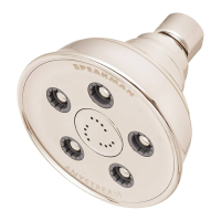
Install shower head onto shower arm and check for leaks.

Service and Repair Information

Service Instructions Overview

Caution that service may affect outlet temperature; reset to 110°F.

Cartridge Removal and Replacement

Steps for shutting off water, removing handle/plate, and replacing cartridge assembly.

Repair Parts List

Lists part numbers for handle and retrofit kit.

Rough-In Diagrams

S-1496-AF Rough-In Diagram

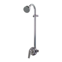
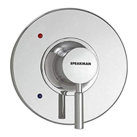
Provides dimensions and connection details for S-1496-AF model.

S-1498-LH Rough-In Diagram

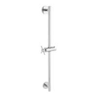
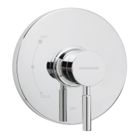
Provides dimensions and connection details for S-1498-LH model.

Overview

The provided document is an installation and service manual for Speakman S-1496-AF and S-1498-LH shower valves. These models appear to be thermostatic or pressure-balancing shower valves, designed to provide a consistent water temperature and flow.

Function Description

The Speakman S-1496-AF and S-1498-LH are shower valves that regulate water temperature and flow for a shower system. They are designed to be used in conjunction with a shower head, and the S-1498-LH model specifically includes a 1/2" NPT Male outlet for the shower arm. The valves feature a cartridge-based design that allows for temperature adjustment and can be configured for either standard or back-to-back installations, where hot and cold water supplies might be reversed. A key feature is the Temperature Limit Stop (TLS), which prevents the water temperature from exceeding a user-defined maximum, enhancing safety and preventing scalding.

Important Technical Specifications

  • Operating Range: 20-80 Psi.
  • Maximum Water Pressure: 125 psi static.
  • Minimum Water Pressure: 20 psi flowing.
  • Minimum Cold Supply Temperature: 40 °F.
  • Maximum Hot Supply Temperature: 160 °F.
  • Shower Head Compatibility: Designed for use with a shower head rated at 1.75 gpm (6.6 L/min) or higher flow rate.
  • Inlet Connections: 1/2" NPT Female for both hot and cold supplies.
  • Outlet Connection (S-1498-LH): 1/2" NPT Male (Shower Arm).
  • Compliance: ASME A112.18.1/CSA B 125.1, ASSE 1016. This indicates compliance with standards for plumbing fixtures, including performance and safety for thermostatic or pressure-balancing valves.
  • Temperature Limit Stop (TLS): Factory set at 110 °F, adjustable by the user.
  • Mounting: Designed for wall mounting, with specific rough-in dimensions provided for both models. A spacer block of 1/2"-9/16" thickness is required between the shower valve and the mounting structure to ensure adequate clearance for inlet supply lines.

Usage Features

  • Temperature Control: The valve allows users to adjust the water temperature, with a safety feature (TLS) to prevent accidental scalding. The handle and dial cap facilitate easy temperature selection.
  • Installation Flexibility: The valve can be installed in standard configurations or "back-to-back" with another valve in a shared space, accommodating reversed hot and cold water supplies. This requires a cartridge adjustment.
  • Shower Arm Strap: The S-1496-AF model includes a shower arm strap for additional support, which is a variable but required mounting location.
  • Handle and Dial Cap: These components are designed for easy removal and re-installation, which is necessary for initial setup, TLS adjustment, and maintenance.
  • Water Supply: The valve connects to standard hot and cold pipe connections, which can be routed through the wall, from the ceiling, or from the floor, offering versatility in plumbing design.

Maintenance Features

  • Cleaning: The manual recommends cleaning the valve periodically with a soft cloth. It explicitly warns against using harsh chemicals and abrasives, as these can damage the finish and void the warranty. Only approved cleaners should be used.
  • Regular Maintenance: This type of valve requires regular cleaning and maintenance, at least every 12 months, or after any changes to the building's plumbing system.
  • Cartridge Access: The cartridge assembly is designed for easy removal, allowing for cleaning, adjustment, or replacement. This involves removing the retaining clip, TLS plate, bonnet screws, and separating the bonnet from the cartridge housing.
  • TLS Adjustment: The Temperature Limit Stop (TLS) should be checked and adjusted quarterly, or as needed, to ensure the maximum hot temperature setting remains safe and accurate. This adjustment is performed by manipulating the TLS plate and retaining clip on the spindle.
  • Freeze Protection (for outdoor installations): For valves installed outdoors, winterization is crucial to prevent freeze damage, which voids the warranty. This involves removing all internal parts (including the valve cartridge and shower head) and draining all standing water from the unit. Stored parts should be kept indoors.
  • Scalding Prevention (for outdoor installations): In outdoor temperatures above 90 degrees, users are cautioned to flush the unit for 30 seconds before showering to prevent scalding from water stored within the unit.
  • Repair Parts: The manual includes a list of repair parts, such as the handle with screw and a retrofit "PB Kit," indicating that components are replaceable for extended product life.

Speakman S-1496-AF Specifications

General IconGeneral
BrandSpeakman
ModelS-1496-AF
CategoryPlumbing Product
LanguageEnglish

Related product manuals